STEERING COLUMN ASSEMBLY REMOVAL
PROCEDURE
PRECAUTION
ALIGN FRONT WHEELS FACING STRAIGHT AHEAD
REMOVE HORN BUTTON ASSEMBLY
REMOVE STEERING WHEEL ASSEMBLY
REMOVE STEERING COLUMN COVER
-
Remove the 2 screws.
-
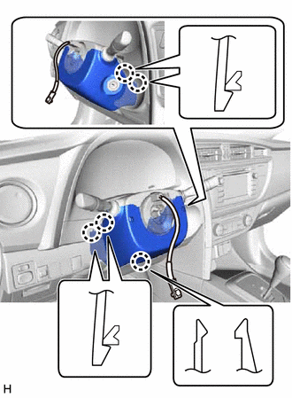
Disengage the 5 claws and remove the steering column cover (lower).
-
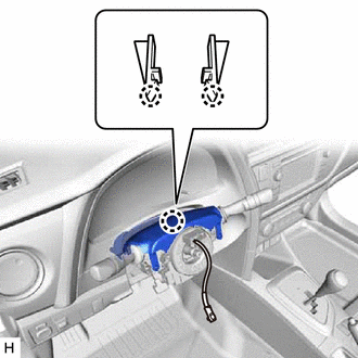
Disengage the 2 claws and remove the steering column cover (upper).
-
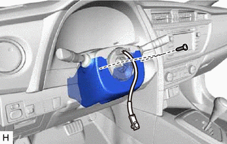
REMOVE TURN SIGNAL SWITCH ASSEMBLY WITH SPIRAL CABLE SUB-ASSEMBLY
Note:w/ VSC:
Do not replace the spiral cable with sensor sub-assembly with the battery connected and the ignition switch ON.
Do not rotate the spiral cable with sensor sub-assembly without the steering wheel with the battery connected and the ignition switch ON.
Ensure that the steering wheel is installed and aligned straight when inspecting the steering sensor.
Disconnect each connector from the turn signal switch assembly with spiral cable sub-assembly.
-
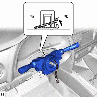
*a
Clamp
*b
Claw
Using pliers, expand the clamp.
While holding the clamp expanded, raise the claw using a screwdriver to disengage it, and then remove the turn signal switch assembly with spiral cable sub-assembly from the steering column assembly.
REMOVE COLUMN HOLE COVER SILENCER SHEET
Turn back the floor carpet.
-
Remove the 2 clips and column hole cover silencer sheet.
SEPARATE NO. 2 STEERING INTERMEDIATE SHAFT ASSEMBLY
-
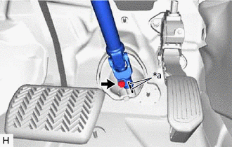
*a
Matchmark
Put matchmarks on the No. 2 steering intermediate shaft assembly and steering intermediate shaft assembly.
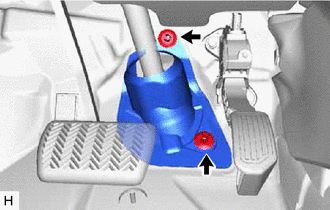
Remove the bolt.
Separate the No. 2 steering intermediate shaft assembly from the steering intermediate shaft assembly.
-
REMOVE NO. 2 STEERING INTERMEDIATE SHAFT ASSEMBLY
-
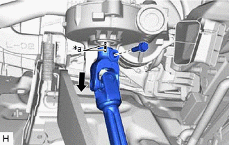
*a
Matchmark
Remove the bolt and slide the No. 2 steering intermediate shaft assembly.
Note:Do not separate the No. 2 steering intermediate shaft assembly from the steering column assembly.
Put matchmarks on the No. 2 steering intermediate shaft assembly and the steering column assembly.
Remove the No. 2 steering intermediate shaft assembly from the steering column assembly.
-
REMOVE BRAKE PEDAL SUPPORT ASSEMBLY
for LHD:Click hereClick here
for RHD:Click here
REMOVE UPPER INSTRUMENT PANEL ASSEMBLY
for Hatchback, Wagon:Click hereClick here
for Sedan:Click hereClick here
REMOVE LOWER INSTRUMENT CLUSTER FINISH PANEL ASSEMBLY (w/o Driver Side Knee Airbag)
for Hatchback LHD, Wagon LHD:Click hereClick here
for Hatchback RHD, Wagon RHD:Click hereClick here
for Sedan LHD:Click hereClick here
for Sedan RHD:Click hereClick here
REMOVE NO. 1 SWITCH HOLE BASE (w/o Driver Side Knee Airbag)
for Hatchback LHD, Wagon LHD:Click hereClick here
for Hatchback RHD, Wagon RHD:Click hereClick here
for Sedan LHD:Click hereClick here
for Sedan RHD:Click hereClick here
REMOVE NO. 1 INSTRUMENT PANEL UNDER COVER SUB-ASSEMBLY (w/o Driver Side Knee Airbag)
w/ Instrument Panel Under Cover:
for Hatchback, Wagon:Click hereClick here
for Sedan:Click hereClick here
REMOVE LOWER INSTRUMENT PANEL FINISH PANEL SUB-ASSEMBLY (w/o Driver Side Knee Airbag)
for Hatchback, Wagon:Click hereClick here
for Sedan:Click hereClick here
REMOVE LOWER NO. 1 INSTRUMENT PANEL AIRBAG ASSEMBLY (w/ Driver Side Knee Airbag)
for Hatchback, Wagon:Click here
for Sedan:Click hereClick here
REMOVE STEERING COLUMN ASSEMBLY
-
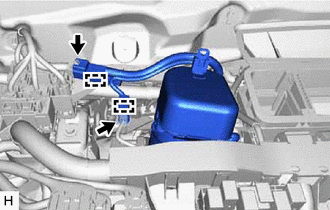
Disconnect the 2 connectors.
Disengage the 2 wire harness clamps.
Disconnect each connector and disengage each wire harness clamp from the steering column assembly.
-
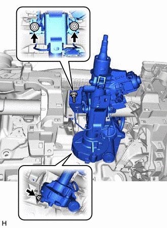
Remove the bolt, 2 nuts and steering column assembly.
-