CONTINUOUSLY VARIABLE TRANSAXLE SYSTEM(for 8NR-FTS), Diagnostic DTC:P070312
| DTC Code | DTC Name |
|---|---|
| P070312 | Brake Switch "B" Circuit Short to Battery |
DESCRIPTION
The purpose of this circuit is to prevent the engine from stalling when the brakes are suddenly applied while driving with lock-up on.
When the brake pedal is depressed, stop light switch assembly sends a signal to the ECM. Then the ECM cancels the operation of the lock-up clutch while braking is in progress.
DTC No. |
Detection Item |
DTC Detection Condition |
Trouble Area |
MIL |
Memory |
Note |
|---|---|---|---|---|---|---|
P070312 |
Brake Switch "B" Circuit Short to Battery |
1. Diagnosis Condition 2. Malfunction Status 3. Malfunction Time 4. Other
|
|
Comes on |
DTC stored |
SAE Code: P0724 |
MONITOR DESCRIPTION
This DTC indicates that the stop light switch is remaining on. When the stop light switch remains on during "stop and go" driving, the ECM interprets this as a malfunction of the stop light switch assembly, illuminates the MIL and stores this DTC. The vehicle must STOP (less than 3 km/h (2 mph)) and GO (30 km/h (19 mph) or more) five times for two consecutive driving cycles in order to store this DTC.
WIRING DIAGRAM
Refer to DTC P05042B.
CAUTION / NOTICE / HINT
Inspect the fuses for circuits related to this system before performing the following procedure.
Using the GTS, the Data List item "Stop Light SW" can be read.
Read freeze frame data using the GTS. The ECM records vehicle and driving condition information as freeze frame data the moment a DTC is stored. When troubleshooting, freeze frame data can help determine if the vehicle was moving or stationary, if the engine was warmed up or not, if the air fuel ratio was lean or rich, and other data from the time the malfunction occurred.
After performing repair, clear the DTCs and perform the following procedure to check that DTCs are not output.
-
Perform the following stop and go drive pattern 5 times:
CAUTION:Perform the following procedure while strictly observing all traffic laws and speed limits.
Accelerate the vehicle to 30 km/h (19 mph) or more, depress the brake pedal and decelerate the vehicle to 3 km/h (2 mph) or less.
Turn the ignition switch off.
Perform step (a) again.
Check for DTCs again.
PROCEDURE
READ VALUE USING GTS (STOP LIGHT SW)
Connect the GTS to the DLC3.
Turn the ignition switch to ON.
Turn the GTS on.
Enter the following menus: Powertrain / Transmission / Data List / Stop Light SW.
According to the display on the GTS, read the Data List.
Powertrain > Transmission > Data List
Tester Display
Measurement Item
Range
Normal Condition
Diagnostic Note
Stop Light SW
Stop light switch status
OFF or ON
OFF: Brake pedal released
ON: Brake pedal depressed
-
Powertrain > Transmission > Data List
Tester Display
Stop Light SW
OK
On the GTS screen, ON or OFF is displayed accordingly.
Note:In the table above, the conditions listed under "Normal Condition" are reference conditions. Do not depend solely on these reference conditions when deciding whether a part is faulty or not.
Result
Proceed to
OK
NG
CHECK STOP LIGHT SWITCH ASSEMBLY INSTALLATION
Check the stop light switch assembly installation.
OK
Stop light switch assembly is installed correctly.
Result
Proceed to
OK
NG
INSPECT STOP LIGHT SWITCH ASSEMBLY
Inspect the stop light switch assembly.
Result
Proceed to
OK
NG
CHECK TERMINAL VOLTAGE (STP VOLTAGE)
Disconnect the A173 ECM connector.
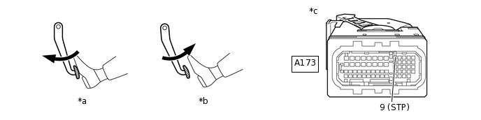
*a
Brake pedal depressed
*b
Brake pedal released
*c
Front view of wire harness connector
(to ECM)
-
-
Measure the voltage according to the value(s) in the table below.
Standard Voltage
Tester Connection
Condition
Specified Condition
A173-9 (STP) - Body ground
Brake pedal released
Below 1.5 V
Brake pedal depressed
7.5 to 14 V
Result
Proceed to
OK
NG
NG REPAIR OR REPLACE HARNESS OR CONNECTOR (STOP LIGHT SWITCH ASSEMBLY - ECM)
REPLACE ECM
Replace the ECM.
Result
Proceed to
NEXT