LANE DEPARTURE ALERT SYSTEM
-
FUNCTION OF MAIN COMPONENTS
Components Function Forward Recognition Camera
-
Captures the road view ahead of the vehicle and detects lane markers on the driving lane, and calculates the radius to the center of the lane, lane width, distance from markers and heading angle deviation.
-
Controls the lane departure alert system.
-
Transmits the indicator illumination request signal, multi-information display indication request signal, and buzzer sound request signal to the combination meter assembly.
-
Transmits an operation signal to the camera heater.*1
Camera Heater (Forward Recognition Hood)*1 The camera heater is heated according to signals from the forward recognition camera. Combination Meter Assembly Multi-information Display
-
The LDA indicator light illuminates, blinks or turns off in accordance with signals from the forward recognition camera.*2
-
Displays a warning message and white lines to inform or warn the driver of the system condition in accordance with signals from the forward recognition camera.
Master Warning Light Illuminates to warn the driver in accordance with signals from the forward recognition camera. Multi Buzzer Sounds to warn the driver in accordance with signals from the forward recognition camera. LDA Indicator Light*3 Illuminates or turns off in accordance with signals from the forward recognition camera. Skid Control ECU Sends a vehicle speed signal from the speed sensor to the forward recognition camera. LDA Main Switch Detects an on/off status of the system and transmits a signal to the forward recognition camera. Airbag Sensor Assembly Yawrate Sensor Detects the yaw rate and transmits a signal to the forward recognition camera. Millimeter Wave Radar Sensor Assembly Radiates millimeter radar waves forward, uses the reflected waves to detect the presence of a vehicle ahead and then transmits this information to the forward recognition camera. Speed Sensors Detects the vehicle speed and transmits a signal via the skid control ECU to the forward recognition camera. Headlight Dimmer Switch Assembly Transmits a turn signal command to the combination meter assembly. Steering Sensor Detects the angle and direction of steering and transmits signals to the forward recognition camera. Central Gateway ECU Transmits the signal between the CAN communication buses. *1: Models with camera heater
*2: Models with Optitron type combination meter assembly
*3: Models with analog type combination meter assembly with dot display type multi-information display
-
-
OPERATION CONDITION
-
Operating Conditions of LDA System (Lane Departure Alert Function)
Operation Condition Operating The lane departure alert function is activated when all of the following conditions are met:
-
The LDA main switch is on.
-
The vehicle speed is above approximately 50 km/h (32 mph) or more.
-
Lane markers are detected.
-
The turn signal light is not operated.
-
No system malfunctions are detected.
Suspended The lane departure alert function is suspended when any one of the following conditions is met:
-
The vehicle speed is less than approximately 50 km/h (32 mph).
-
A turn signal command is detected.
-
No lane markers are detected.
-
Immediately after the lane departure alert is activated.
-
The temperature of the forward recognition camera is abnormal.
-
A malfunction is detected in the LDA system.
-
The vehicle crosses halfway or further over a lane marker.
Canceled/Resume The lane departure alert function is stopped when any one of the following conditions is met:
-
The LDA main switch is off.
-
The LDA system is malfunctioning.
-
The ignition switch is turned off.
The lane departure alert function resumes when the following conditions are met:
-
The conditions to start operation listed above are satisfied.
-
The LDA system condition returns to normal.
-
The ignition switch is turned off and to ON again to ensure normal operation, after the LDA system has been stopped by a system malfunction.
-
-
Operating Conditions of LDA System (Vehicle Sway Warning Function)
Operation Condition Operating The vehicle sway warning function is activated when all of the following conditions are met:
-
The LDA main switch is on.
-
The vehicle speed is above approximately 50 km/h (32 mph) or more.
-
Lane markers are detected.
-
The turn signal light is not operated.
-
No system malfunctions are detected.
Suspended The vehicle sway warning function is suspended when any one of the following conditions is met:
-
The vehicle speed is less than approximately 50 km/h (32 mph).
-
A turn signal command is detected.
-
No lane markers are detected.
-
The temperature of the forward recognition camera is abnormal.
-
A malfunction is detected in the LDA system.
Canceled/Resume The vehicle sway warning function is stopped when any one of the following conditions is met:
-
The LDA main switch is off.
-
The LDA system is malfunctioning.
-
The ignition switch is turned off.
The vehicle sway warning function resumes when the following conditions are met:
-
The conditions to start operation listed above are satisfied.
-
The LDA system condition returns to normal.
-
The ignition switch is turned off and to ON again to ensure normal operation, after the LDA system has been stopped by a system malfunction.
-
-
-
SYSTEM CONTROL
-
LDA System Warning Operation
-
Function Over View (Lane Departure Alert Function)
-
If the system judges that the vehicle may deviate from the lane it is in, the system blinks the lane marker on the multi-information display and sounds a buzzer so that the driver can take action to avoid lane departure.
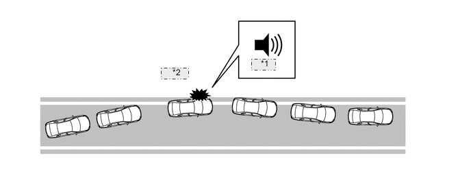
*1 Buzzer *2 Warning -
-
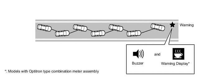
Function Over View (Vehicle Sway Warning Function)
-
The system detects drift of the vehicle within its lane, which is often the result of a driver who is tired, distracted or not looking ahead, based on the position of the vehicle within its lane and the steering inputs of the driver, and alerts the driver before a lane departure or collision occurs.
-
-
-
-
DIAGNOSIS
-
If a malfunction is detected in the LDA system, the forward recognition camera cancels the LDA system, turns on the LDA indicator light (amber)*1 or turns off*2 the LDA indicator light, illuminates the master warning light, sounds the buzzer in the combination meter assembly, and displays a message on the multi-information display to inform the driver of the malfunction.
-
*1: Models with Optitron type combination meter assembly
-
*2: Models with analog type combination meter assembly with dot display type multi-information display
-
-
At the same time, the malfunction is stored in memory as a Diagnostic Trouble Code (DTC). When the Global TechStream (GTS) is connected to the DLC3, the DTC can be read. For details, refer to the Repair Manual.
-