FUEL TANK(for Rear Air Fuel Ratio Sensor) INSTALLATION
PROCEDURE
-
INSTALL CHECK VALVE BRACKET (w/ Canister Pump Module)
-
Engage the clamp to install the check valve bracket to the fuel tank assembly.
-
-
INSTALL NO. 6 FUEL TANK CUSHION (w/ Canister Pump Module)
-
Install the No. 6 fuel tank cushion to the fuel tank assembly.
-
-
INSTALL TANK SUCTION TUBE SUPPORT
-
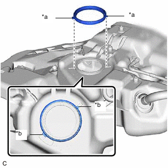
*a Protrusion *b Notch Install a new tank suction tube support to the fuel tank assembly.
Tech Tips
Align the protrusions of the tank suction tube support with the notches of the fuel tank assembly.
-
-
INSTALL FUEL TANK CUSHION SET
-
Install the 2 fuel tank cushion sets and 2 No. 5 fuel tank cushions to the fuel tank assembly.
-
-
INSTALL FUEL TANK MAIN TUBE SUB-ASSEMBLY
-
Engage the 3 claws to install the fuel tank main tube sub-assembly to the fuel tank assembly.
-
-
INSTALL REAR FUEL TANK SIDE PLATE
-
Install a new rear fuel tank side plate to the fuel tank assembly with the fuel tank cushion.
-
-
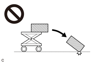
INSTALL FUEL TANK ASSEMBLY
CAUTION:
The fuel tank assembly is very heavy. Be sure to follow the procedure described in the repair manual, or the fuel tank assembly may fall off the engine lifter.
-
Set the fuel tank assembly on an engine lifter.
Tech Tips
Using height adjustment attachments and plate lift attachments, keep the fuel tank assembly horizontal.
-
Using the engine lifter, slowly raise the fuel tank assembly, and then install the fuel tank assembly, No. 1 fuel tank band sub-assembly LH and No. 1 fuel tank band sub-assembly RH with the 4 bolts.
- Torque:
- 45 N*m { 459 kgf*cm, 33 ft.*lbf }
Note
-
Be careful not to drop the fuel tank assembly.
-
When installing the fuel tank assembly, tilt it slightly to prevent it from interfering with the surrounding parts.
-
Install the nut.
- Torque:
- 19.6 N*m { 200 kgf*cm, 14 ft.*lbf }
-
Install the rear fuel tank mounting bracket with the bolt and nut.
- Torque:
- Bolt
- 45 N*m { 459 kgf*cm, 33 ft.*lbf }
- Nut
- 19.6 N*m { 200 kgf*cm, 14 ft.*lbf }
-
-
CONNECT FUEL TANK EVAP/VENT TUBE SUB-ASSEMBLY (w/ Canister Pump Module)
-
Connect the fuel tank evap/vent tube sub-assembly to the charcoal canister assembly.
-
-
CONNECT FUEL CUT OFF VALVE WITH TUBE ASSEMBLY (w/o Canister Pump Module)
-
Connect the fuel cut off valve with tube assembly to the charcoal canister assembly.
-
-
CONNECT FUEL TANK INLET TUBE SUB-ASSEMBLY
-
Connect the fuel tank inlet tube sub-assembly to the fuel tank filler pipe assembly.
-
-
CONNECT FUEL TANK BREATHER TUBE
-
Connect the fuel tank breather tube to the fuel pipe.
-
-
CONNECT FUEL TANK MAIN TUBE SUB-ASSEMBLY
-
Connect the fuel tank main tube sub-assembly to the fuel pipe.
-
-
INSTALL NO. 1 FUEL TANK PROTECTOR SUB-ASSEMBLY
-
Install the No. 1 fuel tank protector sub-assembly with the 4 nuts and 4 new clips.
- Torque:
- 5.5 N*m { 56 kgf*cm, 49 in.*lbf }
-
-
INSTALL CHARCOAL CANISTER PROTECTOR (w/ Canister Pump Module)
-
INSTALL CHARCOAL CANISTER PROTECTOR (w/o Canister Pump Module)
-
INSTALL FRONT CENTER FLOOR COVER
-
Engage the 4 clips to install the front center floor cover.
-
Install the 2 screws and nut.
-
-
INSTALL REAR SUSPENSION MEMBER SUB-ASSEMBLY (for 2WD)
-
INSTALL REAR SUSPENSION MEMBER SUB-ASSEMBLY (for AWD)
-
INSTALL FUEL SUCTION TUBE WITH PUMP AND GAUGE ASSEMBLY
-
ADD FUEL