INTEGRATION RELAY INSTALLATION
PROCEDURE
-
INSTALL SEMICONDUCTOR POWER INTEGRATION ECU
-
Connect the 5 connectors.
-
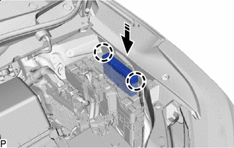

Install in this Direction Engage the 2 claws to install the semiconductor power integration ECU as shown in the illustration.
-
-
INSTALL NO. 1 RELAY BLOCK COVER
-
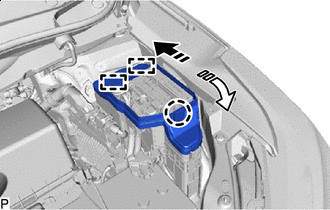
Install in this Direction (1) 
Install in this Direction (2) Engage the 2 guides and claw to install the No. 1 relay block cover as indicated by the arrows, in the order shown in the illustration.
-
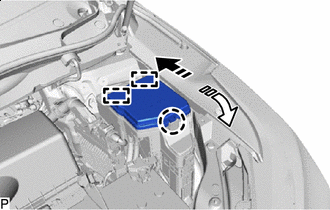
Install in this Direction (1) Install in this Direction (2) Engage the 2 guides and claw to install the No. 1 relay block cover as indicated by the arrows, in the order shown in the illustration.
-
-
INSTALL RESERVOIR BRACKET (for LHD)
-
CONNECT BRAKE MASTER CYLINDER RESERVOIR ASSEMBLY (for LHD)
-
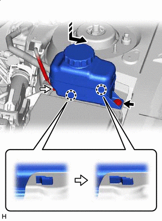

Bolt 
Connector Install in this Direction Move the brake master cylinder reservoir assembly as shown in the illustration to engage the 2 claws.
-
Connect the reservoir level switch connector and install the bolt.
- Torque:
- 9.0 N*m { 92 kgf*cm, 80 in.*lbf }
-
-
CONNECT CABLE FROM NEGATIVE BATTERY TERMINAL
Note
When disconnecting the cable, some systems need to be initialized after the cable is reconnected.