TIRE PRESSURE WARNING SYSTEM ECU Power Source Circuit
| DTC Code | DTC Name |
|---|---|
| ECU Power Source Circuit |
DESCRIPTION
The IG circuit is the power source for the tire pressure warning ECU and receiver.
WIRING DIAGRAM
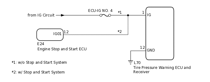
CAUTION / NOTICE / HINT
When replacing the tire pressure warning ECU and receiver, read the transmitter IDs stored in the old ECU using the GTS and write them down before removal.
It is necessary to perform initializationClick hereafter registrationClick hereof the transmitter IDs into the tire pressure warning ECU and receiver if the ECU has been replaced.
Inspect the fuses for circuits related to this system before performing the following inspection procedure.
PROCEDURE
CHECK HARNESS AND CONNECTOR (ECU - BATTERY AND BODY GROUND)
-
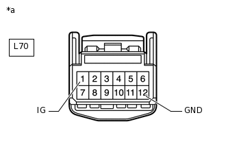
*a
Front view of wire harness connector
(to Tire Pressure Warning ECU and Receiver)
Disconnect the L70 tire pressure warning ECU and receiver connector.
Measure the voltage according to the value(s) in the table below.
Standard Voltage
Tester Connection
Condition
Specified Condition
L70-1 (IG) - Body ground
Ignition switch ON
10 to 16 V
Ignition switch off
Below 1 V
Measure the resistance according to the value(s) in the table below.
Standard Resistance
Tester Connection
Condition
Specified Condition
L70-12 (GND) - Body ground
Always
Below 1 Ω
Result
Proceed to
OK
NG
NG REPAIR OR REPLACE HARNESS OR CONNECTOR
-