LIGHTING SYSTEM Engine Switch Illumination Circuit
DESCRIPTION
The illuminated entry system controls the engine switch illumination.
WIRING DIAGRAM
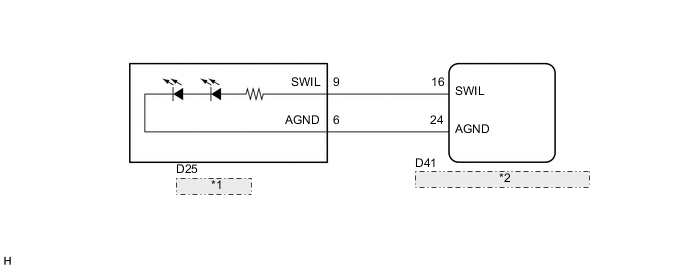
| *1 | Engine Switch |
| *2 | Certification ECU (Smart Key ECU Assembly) |
CAUTION / NOTICE / HINT
Note
-
Before performing the following inspection, check that the engine switch illumination has not been turned off using the rheostat function.
-
The engine switch illumination can be turned off by using the rheostat knob to select the minimum illuminance level with the taillights on.
PROCEDURE
-
PERFORM ACTIVE TEST USING GTS
-
Connect the GTS to the DLC3.
-
Turn the ignition switch to ON.
-
Turn the GTS on.
-
Enter the following menus: Body Electrical / Main Body / Active Test.
-
Check that the illumination operates.
OK Engine switch illumination comes on. Main Body Tester Display Test Part Control Range Diagnostic Note Illuminated Entry System Engine switch illumination ON/OFF -
OK 
PROCEED TO NEXT SUSPECTED AREA SHOWN IN PROBLEM SYMPTOMS TABLE Click here
NG 
-
-
INSPECT ENGINE SWITCH
-
Remove the engine switch Click here.
-
Inspect the engine switch Click here.
OK Engine switch illumination comes on.
NG
REPLACE ENGINE SWITCH Click here
OK
-
-
CHECK HARNESS AND CONNECTOR (ENGINE SWITCH - CERTIFICATION ECU (SMART KEY ECU ASSEMBLY))
-
Disconnect the D41 certification ECU (smart key ECU assembly) connector.
-
Disconnect the D25 engine switch connector.
-
Measure the resistance according to the value(s) in the table below.
Standard Resistance Tester Connection Condition Specified Condition D41-16 (SWIL) - D25-9 (SWIL) Always Below 1 Ω D41-24 (AGND) - D25-6 (AGND) Always Below 1 Ω D41-16 (SWIL) - Body ground Always 10 kΩ or higher D41-24 (AGND) - Body ground Always Below 1 Ω
OK
REPLACE CERTIFICATION ECU (SMART KEY ECU ASSEMBLY)
NG
REPAIR OR REPLACE HARNESS OR CONNECTOR
-