METER / GAUGE SYSTEM Speed Signal Circuit
| DTC Code | DTC Name |
|---|---|
| Speed Signal Circuit |
DESCRIPTION
The vehicle speed signal consists of pulses sent to the combination meter assembly from the skid control ECU.
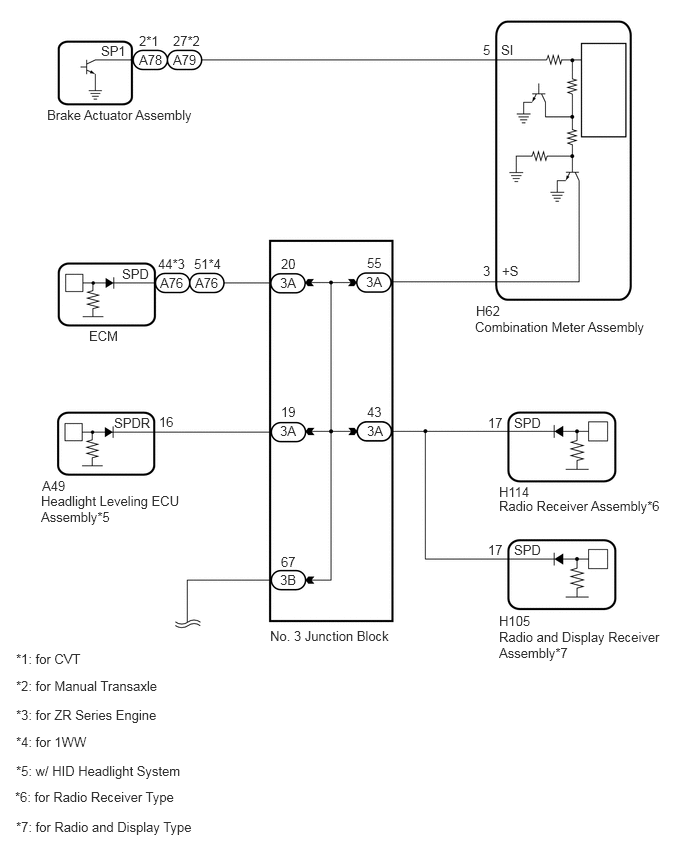
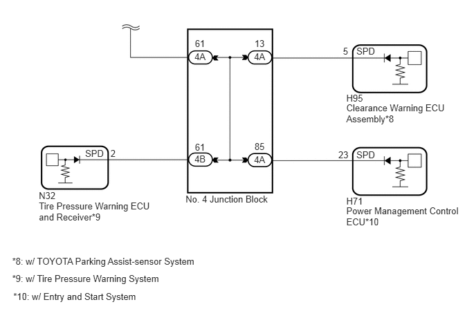
WIRING DIAGRAM
PROCEDURE
CHECK ECU TERMINAL VOLTAGE (INPUT VOLTAGE)
-
Disconnect the combination meter assembly connector.
Measure the voltage according to the value(s) in the table below.
Standard Voltage
Tester Connection
Switch Condition
Specified Condition
H62-3 (+S) - Body ground
Ignition switch ON
4.5 to 14 V
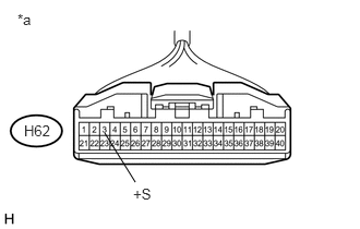
Table 1. Text in Illustration *a
Front view of wire harness connector
(to Combination Meter Assembly)
CHECK HARNESS AND CONNECTOR (COMBINATION METER ASSEMBLY - NO. 3 JUNCTION BLOCK)Click here
-
CHECK COMBINATION METER ASSEMBLY (OUTPUT VOLTAGE)
Disconnect the brake actuator assembly (skid control ECU) connector.
*1: for CVT
*2: for Manual Transaxle
Measure the voltage according to the value(s) in the table below.
Standard Voltage
Table 2. for CVT Tester Connection
Switch Condition
Specified Condition
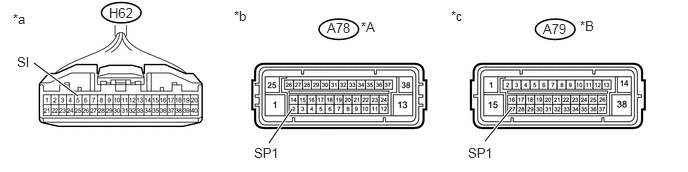
A78-2 (SP1) - Body ground
Ignition switch ON
11 to 14 V
Table 3. for Manual Transaxle Tester Connection
Switch Condition
Specified Condition
A79-27 (SP1) - Body ground
Ignition switch ON
11 to 14 V
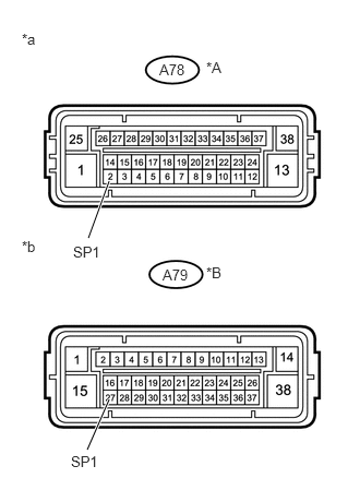
Table 4. Text in Illustration *A
for CVT
*B
for Manual Transaxle
*a
Front view of wire harness connector
(to Brake Actuator Assembly [Skid Control ECU])
*b
Front view of wire harness connector
(to Brake Actuator Assembly [Skid Control ECU])
CHECK HARNESS AND CONNECTOR (COMBINATION METER ASSEMBLY - BRAKE ACTUATOR ASSEMBLY)Click here
CHECK COMBINATION METER ASSEMBLY (SPEED SIGNAL)
-
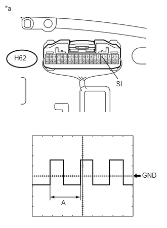
Check the input waveform.
Reconnect the H62 combination meter assembly connector.
Remove the combination meter assembly with the connector(s) still connected.
Connect an oscilloscope to terminal H62-5 (SI) and body ground.
Turn the ignition switch to ON.
Check the signal waveform according to the condition(s) in the table below.
Table 5. Measurement Condition Item
Condition
Terminal No. (Symbol)
H62-5 (SI) - Body ground
Tool setting
5 V/DIV., 20 ms./DIV.
Condition
Being driven at approximately 20 km/h (12 mph)
OK
The waveform displayed is as shown in the illustration.
Table 6. Text in Illustration *a
Component with harness connected
(Combination Meter Assembly)
Tip:When the system is functioning normally, one wheel revolution generates 4 pulses. As the vehicle speed increases, the width indicated by (A) in the illustration narrows.
-
CHECK HARNESS AND CONNECTOR (COMBINATION METER ASSEMBLY - BRAKE ACTUATOR ASSEMBLY)
Disconnect the combination meter assembly connector.
Disconnect the brake actuator assembly (skid control ECU) connector.
*1: for CVT
*2: for Manual Transaxle
Measure the resistance according to the value(s) in the table below.
Standard Resistance
Table 7. for CVT Tester Connection
Condition
Specified Condition
H62-5 (SI) - A78-2 (SP1)
Always
Below 1 Ω
A78-2 (SP1) - Body ground
Always
10 kΩ or higher
Table 8. for Manual Transaxle Tester Connection
Condition
Specified Condition
H62-5 (SI) - A79-27 (SP1)
Always
Below 1 Ω
A79-27 (SP1) - Body ground
Always
10 kΩ or higher
Table 9. Text in Illustration *A
for CVT
*B
for Manual Transaxle
*a
Front view of wire harness connector
(to Combination Meter Assembly)
*b
Front view of wire harness connector
(to Brake Actuator Assembly [Skid Control ECU])
*c
Front view of wire harness connector
(to Brake Actuator Assembly [Skid Control ECU])
REPAIR OR REPLACE HARNESS OR CONNECTOR
CHECK HARNESS AND CONNECTOR (COMBINATION METER ASSEMBLY - NO. 3 JUNCTION BLOCK)
Disconnect the combination meter assembly connector.
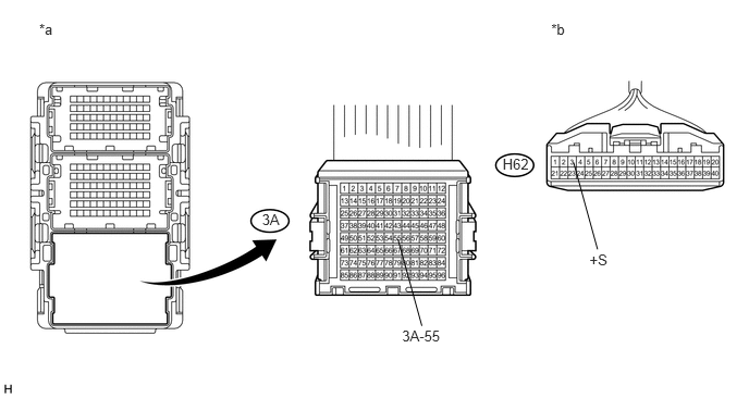
Table 10. Text in Illustration *a
Front view of wire harness connector
(to No. 3 Junction Block)
*b
Front view of wire harness connector
(to Combination Meter Assembly)
Disconnect the No. 3 junction block connector.
Measure the resistance according to the value(s) in the table below.
Standard Resistance
Tester Connection
Condition
Specified Condition
H62-3 (+S) - 3A-55
Always
Below 1 Ω
H62-3 (+S) - Body ground
Always
10 kΩ or higher
Table 11. Result Result
Proceed to
OK (w/ Entry and start system, TOYOTA parking assist-sensor system or tire pressure warning system)
A
OK (w/o Entry and start system, TOYOTA parking assist-sensor system and tire pressure warning system)
B
NG
C
CHECK POWER MANAGEMENT CONTROL ECU
Disconnect the No. 3 junction block connector.
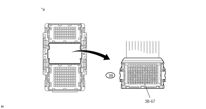
Table 12. Text in Illustration *a
Front view of wire harness connector
(to No. 3 Junction Block)
-
-
Measure the voltage according to the value(s) in the table below.
Standard Voltage
Tester Connection
Switch Condition
Specified Condition
3B-67 - Body ground
Ignition switch ON
4.5 to 14 V
CHECK HARNESS AND CONNECTOR (NO. 3 JUNCTION BLOCK - NO. 4 JUNCTION BLOCK)Click here
CHECK RADIO RECEIVER ASSEMBLY
Note:For vehicles radio and display type, go to "Check Radio and Display Receiver Assembly".
Disconnect the No. 3 junction block connector.
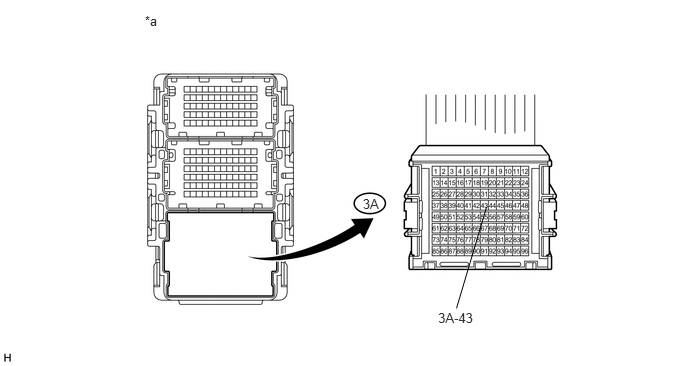
Table 13. Text in Illustration *a
Front view of wire harness connector
(to No. 3 Junction Block)
-
-
Measure the voltage according to the value(s) in the table below.
Standard Voltage
Tester Connection
Switch Condition
Specified Condition
3A-43 - Body ground
Ignition switch ON
4.5 to 14 V
CHECK HARNESS AND CONNECTOR (RADIO RECEIVER ASSEMBLY CIRCUIT)Click here
CHECK RADIO AND DISPLAY RECEIVER ASSEMBLY
Note:For vehicles radio receiver type, go to "Check Headlight Leveling ECU Assembly".
Disconnect the No. 3 junction block connector.
Table 14. Text in Illustration *a
Front view of wire harness connector
(to No. 3 Junction Block)
-
-
Measure the voltage according to the value(s) in the table below.
Standard Voltage
Tester Connection
Switch Condition
Specified Condition
3A-43 - Body ground
Ignition switch ON
4.5 to 14 V
CHECK HARNESS AND CONNECTOR (RADIO AND DISPLAY RECEIVER ASSEMBLY CIRCUIT)Click here
CHECK HEADLIGHT LEVELING ECU ASSEMBLY
Note:For vehicles without an HID headlight system, go to "Check ECM".
Disconnect the No. 3 junction block connector.

Table 15. Text in Illustration *a
Front view of wire harness connector
(to No. 3 Junction Block)
-
-
Measure the voltage according to the value(s) in the table below.
Standard Voltage
Tester Connection
Switch Condition
Specified Condition
3A-19 - Body ground
Ignition switch ON
4.5 to 14 V
CHECK HARNESS AND CONNECTOR (HEADLIGHT LEVELING ECU ASSEMBLY CIRCUIT)Click here
CHECK ECM
Disconnect the No. 3 junction block connector.

Table 16. Text in Illustration *a
Front view of wire harness connector
(to No. 3 Junction Block)
-
-
Measure the voltage according to the value(s) in the table below.
Standard Voltage
Tester Connection
Switch Condition
Specified Condition
3A-20 - Body ground
Ignition switch ON
4.5 to 14 V
REPLACE NO. 3 JUNCTION BLOCK
CHECK HARNESS AND CONNECTOR (ECM CIRCUIT)Click here
CHECK HARNESS AND CONNECTOR (NO. 3 JUNCTION BLOCK - NO. 4 JUNCTION BLOCK)
Disconnect the No. 3 junction block connector.
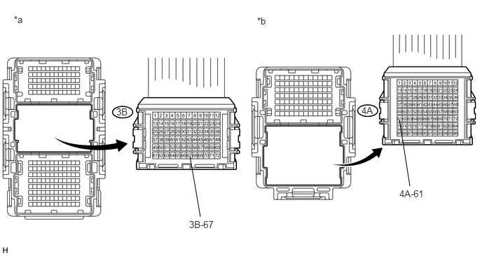
Table 17. Text in Illustration *a
Front view of wire harness connector
(to No. 3 Junction Block)
*b
Front view of wire harness connector
(to No. 4 Junction Block)
Disconnect the No. 4 junction block connector.
Measure the resistance according to the value(s) in the table below.
Standard Resistance
Tester Connection
Condition
Specified Condition
3B-67 - 4A-61
Always
Below 1 Ω
3B-67 - Body ground
Always
10 kΩ or higher
REPAIR OR REPLACE HARNESS OR CONNECTOR
CHECK NO. 4 JUNCTION BLOCK
Disconnect the No. 4 junction block connectors.
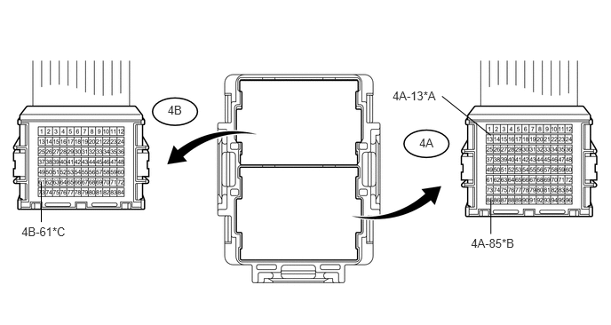
Table 18. Text in Illustration *A
w/ TOYOTA Parking Assist-sensor System
*B
w/ Entry and Start System
*C
w/ Tire Pressure Warning System
-
-
*a
Front view of wire harness connector
(to No. 4 Junction Block)
-
-
Measure the voltage according to the value(s) in the table below.
Standard Voltage
Tester Connection
Switch Condition
Specified Condition
4A-13 - Body ground*1
Ignition switch ON
4.5 to 14 V
4A-85 - Body ground*2
Ignition switch ON
4.5 to 14 V
4B-61 - Body ground*3
Ignition switch ON
4.5 to 14 V
*1: w/ TOYOTA Parking Assist-sensor System
*2: w/ Entry and Start System
*3: w/ Tire Pressure Warning System
Table 19. Result Result
Proceed to
NG (4A-85)
A
NG (4A-13)
B
NG (4B-61)
C
OK
D
CHECK HARNESS AND CONNECTOR (CLEARANCE WARNING ECU ASSEMBLY CIRCUIT)Click here
CHECK HARNESS AND CONNECTOR (TIRE PRESSURE WARNING ECU AND RECEIVER CIRCUIT)Click here
REPLACE NO. 4 JUNCTION BLOCK
CHECK HARNESS AND CONNECTOR (POWER MANAGEMENT CONTROL ECU CIRCUIT)
Disconnect the No. 4 junction block connector.
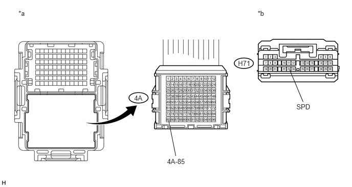
Table 20. Text in Illustration *a
Front view of wire harness connector
(to No. 4 Junction Block)
*b
Front view of wire harness connector
(to Power Management Control ECU)
Disconnect the power management control ECU connector.
Measure the resistance according to the value(s) in the table below.
Standard Resistance
Tester Connection
Condition
Specified Condition
H71-23 (SPD) - 4A-85
Always
Below 1 Ω
4A-85 - Body ground
Always
10 kΩ or higher
Table 21. Result Result
Proceed to
OK (for LHD)
A
OK (for RHD)
B
NG
C
REPAIR OR REPLACE HARNESS OR CONNECTOR
CHECK HARNESS AND CONNECTOR (RADIO RECEIVER ASSEMBLY CIRCUIT)
Disconnect the No. 3 junction block connector.

Table 22. Text in Illustration *a
Front view of wire harness connector
(to No. 3 Junction Block)
*b
Front view of wire harness connector
(to Radio Receiver Assembly)
Disconnect the radio receiver assembly connector.
Measure the resistance according to the value(s) in the table below.
Standard Resistance
Tester Connection
Condition
Specified Condition
H114-17 (SPD) - 3A-43
Always
Below 1 Ω
3A-43 - Body ground
Always
10 kΩ or higher
REPAIR OR REPLACE HARNESS OR CONNECTOR
CHECK HARNESS AND CONNECTOR (RADIO AND DISPLAY RECEIVER ASSEMBLY CIRCUIT)
Disconnect the No. 3 junction block connector.
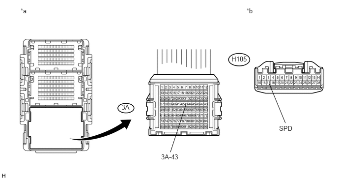
Table 23. Text in Illustration *a
Front view of wire harness connector
(to No. 3 Junction Block)
*b
Front view of wire harness connector
(to Radio and Display Receiver Assembly)
Disconnect the radio and display receiver assembly connector.
Measure the resistance according to the value(s) in the table below.
Standard Resistance
Tester Connection
Condition
Specified Condition
H105-17 (SPD) - 3A-43
Always
Below 1 Ω
3A-43 - Body ground
Always
10 kΩ or higher
REPAIR OR REPLACE HARNESS OR CONNECTOR
CHECK HARNESS AND CONNECTOR (HEADLIGHT LEVELING ECU ASSEMBLY CIRCUIT)
Disconnect the No. 3 junction block connector.
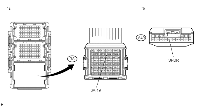
Table 24. Text in Illustration *a
Front view of wire harness connector
(to No. 3 Junction Block)
*b
Front view of wire harness connector
(to Headlight Leveling ECU Assembly)
Disconnect the headlight leveling ECU assembly connector.
Measure the resistance according to the value(s) in the table below.
Standard Resistance
Tester Connection
Condition
Specified Condition
A49-16 (SPDR) - 3A-19
Always
Below 1 Ω
3A-19 - Body ground
Always
10 kΩ or higher
Table 25. Result Result
Proceed to
OK (for LHD)
A
OK (for RHD)
B
NG
C
REPAIR OR REPLACE HARNESS OR CONNECTOR
CHECK HARNESS AND CONNECTOR (ECM CIRCUIT)
Disconnect the No. 3 junction block connector.
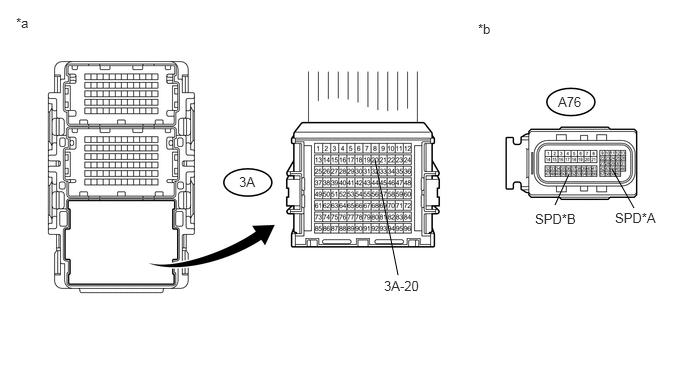
Table 26. Text in Illustration *A
for ZR Series Engine
*B
for 1WW
*a
Front view of wire harness connector
(to No. 3 Junction Block)
*b
Front view of wire harness connector
(to ECM)
Disconnect the ECM connector.
Measure the resistance according to the value(s) in the table below.
Standard Resistance
Table 27. for ZR Series Engine Tester Connection
Condition
Specified Condition
A76-44 (SPD) - 3A-20
Always
Below 1 Ω
3A-20 - Body ground
Always
10 kΩ or higher
Table 28. for 1WW Tester Connection
Condition
Specified Condition
A76-51 (SPD) - 3A-20
Always
Below 1 Ω
3A-20 - Body ground
Always
10 kΩ or higher
Tip:*: Replacement procedure:
for 1ZR-FAE (Click here)
for 2ZR-FAE (Click here)
for 1WW (Click here)
REPLACE ECM*
REPAIR OR REPLACE HARNESS OR CONNECTOR
CHECK HARNESS AND CONNECTOR (CLEARANCE WARNING ECU ASSEMBLY CIRCUIT)
Disconnect the No. 4 junction block connector.
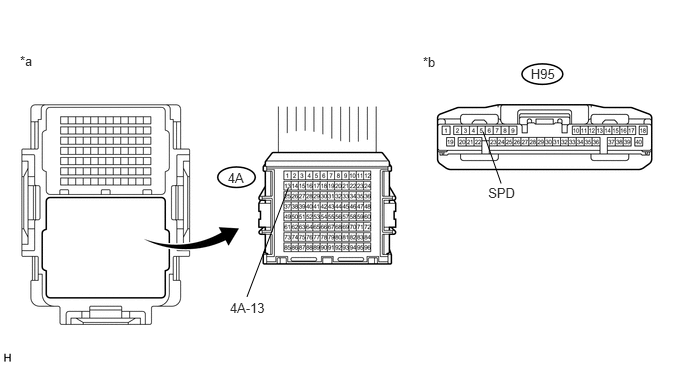
Table 29. Text in Illustration *a
Front view of wire harness connector
(to No. 4 Junction Block)
*b
Front view of wire harness connector
(to Clearance Warning ECU Assembly)
Disconnect the clearance warning ECU assembly connector.
Measure the resistance according to the value(s) in the table below.
Standard Resistance
Tester Connection
Condition
Specified Condition
H95-5 (SPD) - 4A-13
Always
Below 1 Ω
4A-13 - Body ground
Always
10 kΩ or higher
REPAIR OR REPLACE HARNESS OR CONNECTOR
CHECK HARNESS AND CONNECTOR (TIRE PRESSURE WARNING ECU AND RECEIVER CIRCUIT)
Disconnect the No. 4 junction block connector.
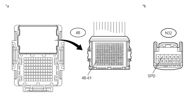
Table 30. Text in Illustration *a
Front view of wire harness connector
(to No. 4 Junction Block)
*b
Front view of wire harness connector
(to Tire Pressure Warning ECU and Receiver)
Disconnect the tire pressure warning ECU and receiver connector.
Measure the resistance according to the value(s) in the table below.
Standard Resistance
Tester Connection
Condition
Specified Condition
N32-2 (SPD) - 4B-61
Always
Below 1 Ω
4B-61 - Body ground
Always
10 kΩ or higher
REPAIR OR REPLACE HARNESS OR CONNECTOR