NAVIGATION SYSTEM Microphone Circuit between Microphone and Radio Receiver
| DTC Code | DTC Name |
|---|---|
| Microphone Circuit between Microphone and Radio Receiver |
DESCRIPTION
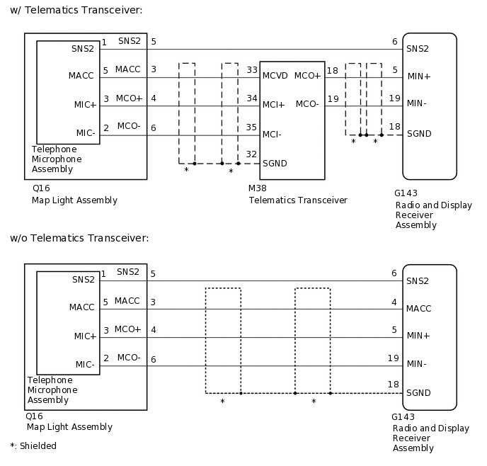
This circuit sends a microphone signal from the telephone microphone assembly to the radio and display receiver assembly.
It also supplies power from the radio and display receiver assembly to the telephone microphone assembly.
WIRING DIAGRAM
CAUTION / NOTICE / HINT
Check that the wire harness is properly installed and does not have any sharp bends, pinching or loose connections.
When replacing telematics transceiver, perform the vehicle contract setting.
PROCEDURE
CONFIRM MODEL
Choose the model to be inspected.
Model
Model
Proceed to
w/o Telematics Transceiver
A
w/ Telematics Transceiver
B
B CHECK HARNESS AND CONNECTOR (RADIO AND DISPLAY RECEIVER ASSEMBLY - MAP LIGHT ASSEMBLY)Click here
CHECK HARNESS AND CONNECTOR (RADIO AND DISPLAY RECEIVER ASSEMBLY - MAP LIGHT ASSEMBLY)
Disconnect the G143 radio and display receiver assembly connector.
Disconnect the Q16 map light assembly connector.
Measure the resistance according to the value(s) in the table below.
Standard Resistance
Tester Connection
Condition
Specified Condition
G143-5 (MIN+) - Q16-4 (MCO+)
Always
Below 1 Ω
G143-4 (MACC) - Q16-3 (MACC)
Always
Below 1 Ω
G143-19 (MIN-) - Q16-6 (MCO-)
Always
Below 1 Ω
G143-6 (SNS2) - Q16-5 (SNS2)
Always
Below 1 Ω
G143-5 (MIN+) - Body ground
Always
10 kΩ or higher
G143-18 (SGND) - Body ground
Always
10 kΩ or higher
G143-4 (MACC) - Body ground
Always
10 kΩ or higher
G143-19 (MIN-) - Body ground
Always
10 kΩ or higher
G143-6 (SNS2) - Body ground
Always
10 kΩ or higher
Result
Proceed to
OK
NG
NG REPAIR OR REPLACE HARNESS OR CONNECTOR
INSPECT MAP LIGHT ASSEMBLY
Remove the map light assembly.
Remove the telephone microphone assembly.
-

*a
Component without harness connected
(Map Light Assembly)
Measure the resistance according to the value(s) in the table below.
Standard Resistance
Tester Connection
Condition
Specified Condition
A-3 (MACC) - B-5 (MACC)
Always
Below 1 Ω
A-4 (MCO+) - B-3 (MIC+)
Always
Below 1 Ω
A-5 (SNS2) - B-1 (SNS2)
Always
Below 1 Ω
A-6 (MCO-) - B-2 (MIC-)
Always
Below 1 Ω
A-3 (MACC) - A-4 (MCO+)
Always
10 kΩ or higher
A-3 (MACC) - A-5 (SNS2)
Always
10 kΩ or higher
A-3 (MACC) - A-6 (MCO-)
Always
10 kΩ or higher
A-4 (MCO+) - A-5 (SNS2)
Always
10 kΩ or higher
A-4 (MCO+) - A-6 (MCO-)
Always
10 kΩ or higher
A-5 (SNS2) - A-6 (MCO-)
Always
10 kΩ or higher
Result
Proceed to
OK
NG
REPLACE TELEPHONE MICROPHONE ASSEMBLY
Replace the telephone microphone assembly with a known good one.
Check if the same problem occurs again.
OK
Malfunction disappears.
Result
Proceed to
OK
NG
OK END (TELEPHONE MICROPHONE ASSEMBLY IS DEFECTIVE)
CHECK HARNESS AND CONNECTOR (RADIO AND DISPLAY RECEIVER ASSEMBLY - MAP LIGHT ASSEMBLY)
Disconnect the G143 radio and display receiver assembly connector.
Disconnect the Q16 map light assembly connector.
Measure the resistance according to the value(s) in the table below.
Standard Resistance
Tester Connection
Condition
Specified Condition
G143-6 (SNS2) - Q16-5 (SNS2)
Always
Below 1 Ω
Result
Proceed to
OK
NG
NG REPAIR OR REPLACE HARNESS OR CONNECTOR
CHECK HARNESS AND CONNECTOR (RADIO AND DISPLAY RECEIVER ASSEMBLY - TELEMATICS TRANSCEIVER)
Disconnect the G143 radio and display receiver assembly connector.
Disconnect the M38 telematics transceiver connector.
Measure the resistance according to the value(s) in the table below.
Standard Resistance
Tester Connection
Condition
Specified Condition
G143-5 (MIN+) - M38-18 (MCO+)
Always
Below 1 Ω
G143-19 (MIN-) - M38-19 (MCO-)
Always
Below 1 Ω
G143-5 (MIN+) - Body ground
Always
10 kΩ or higher
G143-19 (MIN-) - Body ground
Always
10 kΩ or higher
G143-18 (SGND) - Body ground
Always
10 kΩ or higher
Result
Proceed to
OK
NG
NG REPAIR OR REPLACE HARNESS OR CONNECTOR
CHECK HARNESS AND CONNECTOR (TELEMATICS TRANSCEIVER - MAP LIGHT ASSEMBLY)
Disconnect the M38 telematics transceiver connector.
Disconnect the Q16 map light assembly connector.
Measure the resistance according to the value(s) in the table below.
Standard Resistance
Tester Connection
Condition
Specified Condition
M38-33 (MCVD) - Q16-3 (MACC)
Always
Below 1 Ω
M38-34 (MCI+) - Q16-4 (MCO+)
Always
Below 1 Ω
M38-35 (MCI-) - Q16-6 (MCO-)
Always
Below 1 Ω
M38-33 (MCVD) - Body ground
Always
10 kΩ or higher
M38-34 (MCI+) - Body ground
Always
10 kΩ or higher
M38-35 (MCI-) - Body ground
Always
10 kΩ or higher
M38-32 (SGND) - Body ground
Always
10 kΩ or higher
Result
Proceed to
OK
NG
NG REPAIR OR REPLACE HARNESS OR CONNECTOR
INSPECT MAP LAMP SUB-ASSEMBLY
Remove the map light assembly.
Remove the telephone microphone assembly.
-
*a
Component without harness connected
(Map Light Assembly)
Measure the resistance according to the value(s) in the table below.
Standard Resistance
Tester Connection
Condition
Specified Condition
A-3 (MACC) - B-5 (MACC)
Always
Below 1 Ω
A-4 (MCO+) - B-3 (MIC+)
Always
Below 1 Ω
A-5 (SNS2) - B-1 (SNS2)
Always
Below 1 Ω
A-6 (MCO-) - B-2 (MIC-)
Always
Below 1 Ω
A-3 (MACC) - A-4 (MCO+)
Always
10 kΩ or higher
A-3 (MACC) - A-5 (SNS2)
Always
10 kΩ or higher
A-3 (MACC) - A-6 (MCO-)
Always
10 kΩ or higher
A-4 (MCO+) - A-5 (SNS2)
Always
10 kΩ or higher
A-4 (MCO+) - A-6 (MCO-)
Always
10 kΩ or higher
A-5 (SNS2) - A-6 (MCO-)
Always
10 kΩ or higher
Result
Proceed to
OK
NG
CHECK TELEMATICS TRANSCEIVER
Disconnect the Q16 map light assembly connector.
-
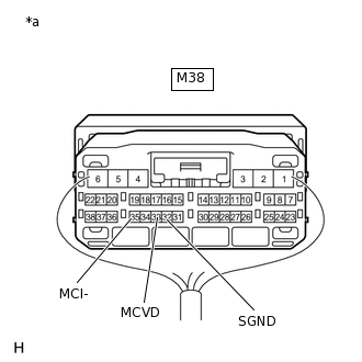
*a
Component with harness connected
(Telematics Transceiver)
Measure the voltage according to the value(s) in the table below.
Standard Voltage
Tester Connection
Switch Condition
Specified Condition
M38-33 (MCVD) - Body ground
Engine switch on (ACC)
4 to 6 V
Measure the resistance according to the value(s) in the table below.
Standard Resistance
Tester Connection
Condition
Specified Condition
M38-32 (SGND) - Body ground
Always
Below 1 Ω
M38-35 (MCI-) - Body ground
Always
Below 1 Ω
Result
Proceed to
OK
NG
REPLACE TELEPHONE MICROPHONE ASSEMBLY
Replace the telephone microphone assembly with a known good one.
Check if the same problem occurs again.
OK
Malfunction disappears.
Result
Proceed to
OK
NG
OK END (TELEPHONE MICROPHONE ASSEMBLY IS DEFECTIVE)