SFI SYSTEM(w/ Canister Pump Module), Diagnostic DTC:P0451,P0452 and P0453
| DTC Code | DTC Name |
|---|---|
| P0451 | Evaporative Emission Control System Pressure Sensor Range / Performance |
| P0452 | Evaporative Emission Control System Pressure Sensor / Switch Low Input |
| P0453 | Evaporative Emission Control System Pressure Sensor / Switch High Input |
DTC SUMMARY
DTC No. |
Detection Item |
DTC Detection Condition |
Trouble Area |
MIL |
Memory |
|---|---|---|---|---|---|
P0451 |
Evaporative Emission Control System Pressure Sensor Range / Performance |
Either of the following conditions is met:
|
|
Comes on |
DTC stored |
P0452 |
Evaporative Emission Control System Pressure Sensor / Switch Low Input |
EVAP pressure sensor less than 42.11 kPa(abs) [315.867 mmHg(abs)] for 0.5 seconds. |
|
Comes on |
DTC stored |
P0453 |
Evaporative Emission Control System Pressure Sensor / Switch High Input |
EVAP pressure sensor higher than 123.761 kPa(abs) [928.331 mmHg(abs)] for 0.5 seconds. |
|
Comes on |
DTC stored |
DTC No. |
Monitoring Item |
Detection Timing |
Detection Logic |
|---|---|---|---|
P0451 |
Canister pressure sensor abnormal voltage fluctuation |
|
2 trip |
Canister pressure sensor constant voltage |
|
2 trip |
|
P0452 |
Canister pressure sensor low input |
|
1 trip |
P0453 |
Canister pressure sensor high input |
|
1 trip |
The canister pressure sensor is built into the canister pump module.
DESCRIPTION
The description can be found in EVAP (Evaporative Emission) System.
MONITOR DESCRIPTION
DTC P0451: Canister pressure sensor abnormal voltage fluctuation or being constant
If the canister pressure sensor voltage output fluctuates rapidly for 10 seconds, the ECM stops the EVAP system monitor. The ECM interprets this as the canister pressure sensor voltage fluctuating, and stops the EVAP system monitor. The ECM then illuminates the MIL and stores the DTC.
Alternatively, if the sensor voltage output does not change for 2 minutes, the ECM interprets this as the sensor being stuck, and stops the monitor. The ECM then illuminates the MIL and stores the DTC.
(Both the malfunctions are detected by 2 trip detection logic).
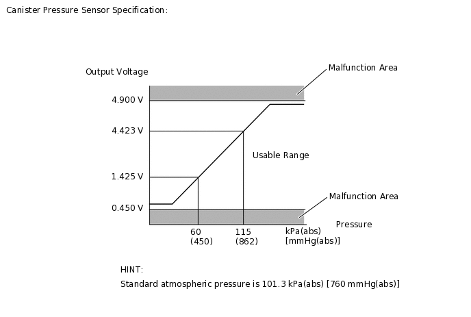
DTC P0452: Canister pressure sensor voltage low
If the canister pressure sensor voltage output (pressure) is less than 0.45 V: 42.11 kPa(abs) [315.867 mmHg(abs)], the ECM interprets this as an open or short circuit in the canister pressure sensor or its circuit, and stops the EVAP system monitor. The ECM then illuminates the MIL and stores the DTC (1 trip detection logic).
DTC P0453: Canister pressure sensor voltage high
If the canister pressure sensor voltage output (pressure) is higher than 4.9 V: 123.761 kPa(abs) [928.331 mmHg(abs)], the ECM interprets this as an open or short circuit in the canister pressure sensor or its circuit, and stops the EVAP system monitor. The ECM then illuminates the MIL and stores the DTC (1 trip detection logic).
MONITOR STRATEGY
Required Sensors/Components |
Canister pump module |
Frequency of Operation |
Continuous |
CONFIRMATION DRIVING PATTERN
The Evaporative System Check (Automatic Mode) consists of 6 steps performed automatically by the GTS. It takes a maximum of approximately 24 minutes.
Do not perform the Evaporative System Check when the fuel tank is higher than 90% full because the cut-off valve may be closed, making the fuel tank leak check unavailable.
Do not run the engine during this operation.
When the temperature of the fuel is 35°C (95°F) or higher, a large amount of vapor forms and any check results become inaccurate. When performing the Evaporative System Check, keep the fuel temperature below 35°C (95°F).
Connect the GTS to the DLC3.
Turn the engine switch on (IG) and turn the GTS on.
Enter the following menus: Powertrain / Engine and ECT / Data List / Primary / Intake Air.
Check that the intake air temperature is between 4.4 and 35°C (40 and 95°F).
Clear the DTCs (even if no DTCs are stored, perform the clear DTC procedure).
Turn the engine switch off and wait for at least 30 seconds.
Turn the engine switch on (IG) and turn the GTS on.
Enter the following menus: Powertrain / Engine and ECT / Utility / Evaporative System Check / Automatic Mode.
After the Evaporative System Check is completed, check for All Readiness by entering the following menus: Powertrain / Engine and ECT / Utility / All Readiness.
Input the DTC: P0451, P0452 or P0453.
Check the DTC judgment result.
GTS Display
Description
NORMAL
DTC judgment completed
System normal
ABNORMAL
DTC judgment completed
System abnormal
INCOMPLETE
DTC judgment not completed
Perform driving pattern after confirming DTC enabling conditions
N/A
Unable to perform DTC judgment
Number of DTCs which do not fulfill DTC preconditions has reached ECU memory limit
Tip:If the judgment result shows NORMAL, the system is normal.
If the judgment result shows ABNORMAL, the system has a malfunction.
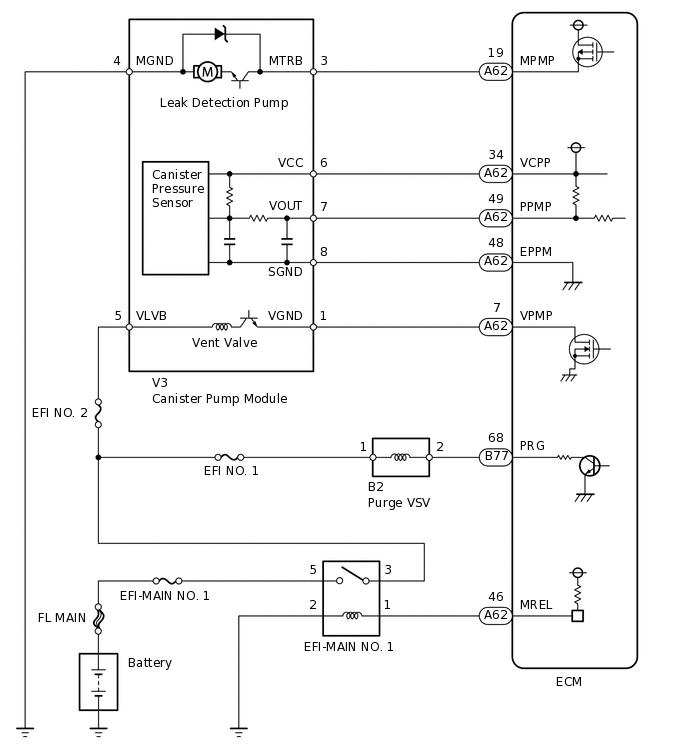
WIRING DIAGRAM
CAUTION / NOTICE / HINT
When a vehicle is brought into the workshop, leave it as it is. Do not change the vehicle condition. For example, do not tighten the fuel tank cap.
The GTS is required to conduct the following diagnostic troubleshooting procedure.
Inspect the fuses for circuits related to this system before performing the following procedure.
PROCEDURE
CONFIRM DTC AND EVAP PRESSURE
Connect the GTS to the DLC3.
Turn the engine switch on (IG) (do not start the engine).
Turn the GTS on.
Enter the following menus: Powertrain / Engine and ECT / Trouble Codes.
Powertrain > Engine and ECT > Trouble Codes
Read the DTCs.
Enter the following menus: Powertrain / Engine and ECT / Data List / Ptrl Evaporative / Vapor Pressure Pump.
Powertrain > Engine and ECT > Data List
Tester Display
Vapor Pressure Pump
Read the EVAP (Evaporative Emission) pressure displayed on the GTS.
Result
Display (DTC Output)
Test Result
Suspected Trouble Area
Proceed to
P0451
-
Canister pressure sensor
C
P0452
Less than 42.11 kPa(abs) [315.867 mmHg(abs)]
Wire harness/connector (ECM - canister pressure sensor)
Canister pressure sensor
Short in ECM circuit
A
P0453
Higher than 123.761 kPa(abs) [928.331 mmHg(abs)]
Wire harness/connector (ECM - canister pressure sensor)
Canister pressure sensor
Open in ECM circuit
B
CHECK HARNESS AND CONNECTOR (CANISTER PUMP MODULE - ECM)
Disconnect the ECM connector.
Measure the resistance according to the value(s) in the table below.
Result
Tester Connection
Condition
Specified Condition
Suspected Trouble Area
Proceed to
A62-49 (PPMP) - Body ground
Always
Below 10 Ω
Wire harness/connector (ECM - canister pressure sensor)
Short in canister pressure sensor circuit
A
10 kΩ or higher
Wire harness/connector (ECM - canister pressure sensor)
Short in ECM circuit
B
B REPLACE ECMClick here
CHECK HARNESS AND CONNECTOR (CANISTER PUMP MODULE - ECM)
Disconnect the canister pump module connector.
Disconnect the ECM connector.
Measure the resistance according to the value(s) in the table below.
Result
Tester Connection
Condition
Specified Condition
Suspected Trouble Area
Proceed to
A62-49 (PPMP) - Body ground
Always
10 kΩ or higher
Short in canister pressure sensor circuit
A
Below 10 Ω
Short in wire harness/connector (ECM - canister pressure sensor)
B
B REPAIR OR REPLACE HARNESS OR CONNECTOR (CANISTER PUMP MODULE - ECM)Click here
REPLACE CHARCOAL CANISTER LEAK DETECTION PUMP SUB-ASSEMBLY (CANISTER PUMP MODULE)
Replace the charcoal canister leak detection pump sub-assembly.
Note:When replacing the canister pump module, check the canister pump module interior, canister interior and related pipes for water, fuel and other liquids. If liquids are present, check for disconnections and/or cracks in the following: 1) the pipe from the air inlet port to the canister pump module; 2) the canister filter; and 3) the fuel tank vent hose. If liquids are present in the canister interior, replace the canister and canister pump module together.
Check for filter blockage in the canister. If the charcoal filter inside the canister is clogged, replace the canister and canister pump module together.
Check for filter blockage in the canister filter. If the canister filter has blockages, replace the canister filter.
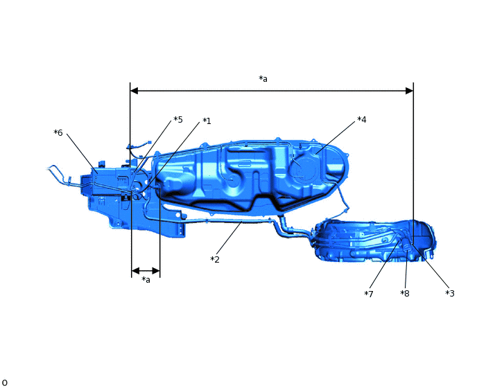
*1
Fuel Tank Vent Hose
*2
Vent Hose
*3
Air Inlet Port
*4
Fuel Tank
*5
Canister Pump Module
*6
Canister Assembly
*7
Fuel Tank Inlet Pipe Sub-assembly (Canister Filter)
*8
Fuel Tank Cap Assembly
*a
Inspection Area
(check for disconnection and/or cracks)
-
-
Result
Proceed to
NEXT
CHECK WHETHER DTC OUTPUT RECURS (AFTER REPAIR)
Connect the GTS to the DLC3.
Turn the engine switch on (IG).
Turn the GTS on.
Clear the DTCs.
Powertrain > Engine and ECT > Clear DTCs
Turn the engine switch off and wait for at least 30 seconds.
Turn the engine switch on (IG).
Turn the GTS on.
Perform the Evaporative System Check using the GTS, referring to the Confirmation Driving Pattern.
Enter the following menus: Powertrain / Engine and ECT / Utility / All Readiness.
Powertrain > Engine and ECT > Utility
Tester Display
All Readiness
Input the DTC: P0452 or P0453.
Check the DTC judgment result.
Result
GTS Display
Description
NORMAL
DTC judgment completed
System normal
ABNORMAL
DTC judgment completed
System abnormal
INCOMPLETE
DTC judgment not completed
Perform driving pattern after confirming DTC enabling conditions
N/A
Unable to perform DTC judgment
Number of DTCs which do not fulfill DTC preconditions has reached ECU memory limit
Result
Proceed to
NEXT
NEXT END
REPAIR OR REPLACE HARNESS OR CONNECTOR (CANISTER PUMP MODULE - ECM)
Tip:If the exhaust pipe has been removed, go to the next step before reinstalling it.
Result
Proceed to
NEXT
NEXT CHECK WHETHER DTC OUTPUT RECURS (AFTER REPAIR)Click here
REPLACE ECM
Replace the ECM.
Result
Proceed to
NEXT
NEXT CHECK WHETHER DTC OUTPUT RECURS (AFTER REPAIR)Click here
CHECK HARNESS AND CONNECTOR (CANISTER PUMP MODULE - ECM)
-
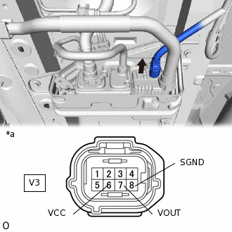
*a
Front view of wire harness connector
(to Canister Pump Module)
Disconnect the canister pump module connector.
Measure the resistance according to the value(s) in the table below.
Standard Resistance
Tester Connection
Condition
Specified Condition
V3-8 (SGND) - Body ground
Always
100 Ω or less
Turn the engine switch on (IG).
Measure the voltage according to the value(s) in the table below.
Standard Voltage
Tester Connection
Switch Condition
Specified Condition
V3-6 (VCC) - Body ground
Engine switch on (IG)
4.5 to 5.5 V
V3-7 (VOUT) - Body ground
Engine switch on (IG)
4.5 to 5.5 V
Result
Test Result
Suspected Trouble Area
Proceed to
Voltage and resistance within standard ranges
Open in canister pressure sensor circuit
A
Voltage and/or resistance outside standard ranges
Open in wire harness/connector (ECM - canister pressure sensor)
B
A REPLACE CHARCOAL CANISTER LEAK DETECTION PUMP SUB-ASSEMBLY (CANISTER PUMP MODULE)Click here
B REPAIR OR REPLACE HARNESS OR CONNECTOR (CANISTER PUMP MODULE - ECM)Click here
-