FIT STANDARD / ADJUSTMENT METHOD ADJUSTMENT
-
INSPECT HOOD SUB-ASSEMBLY
-
Check that the clearance measurements of areas a through e are within each standard range.
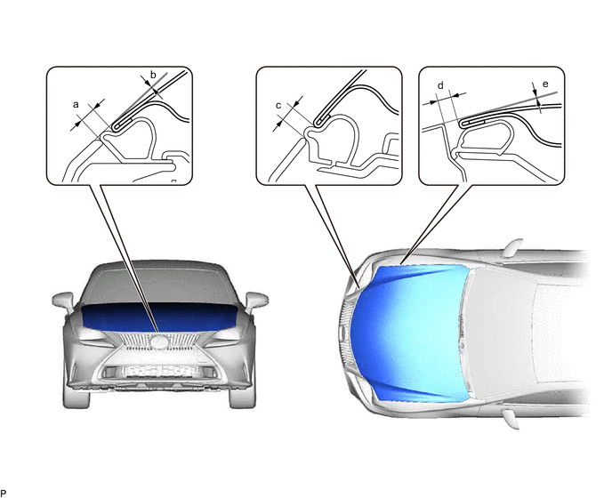
Standard Clearance Area Measurement Area Measurement a 5.0 mm (0.197 in.) b 0.1 mm (0.00394 in.) c 4.5 mm (0.177 in.) d 2.2 to 5.2 mm (0.0866 to 0.205 in.) e -1.3 to 1.7 mm (-0.0512 to 0.0669 in.) - - Tech Tips
Centering bolts are used to mount the hood hinge and hood lock. The hood and hood lock cannot be adjusted with the centering bolts installed. Substitute the centering bolts with standard bolts when making adjustments.
-
-
ADJUST HOOD SUB-ASSEMBLY
-
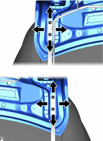
Horizontally and vertically adjust the hood.
-
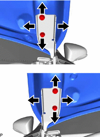
Loosen the 4 hinge bolts of the hood.
-
Adjust the clearance between the hood and front fender by moving the hood.
-
Tighten the 4 hinge bolts after adjustment.
- Torque:
- 13 N*m { 133 kgf*cm, 10 ft.*lbf }
-
-
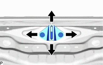
Adjust the height of the front end of the hood using the hood bumper cushions.
-
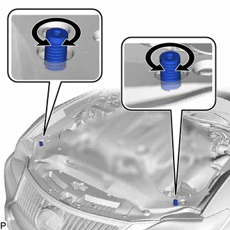
Adjust the 2 hood bumper cushions so that the heights of the hood and fenders are aligned.
Tech Tips
Raise or lower the front end of the hood by turning the 2 hood bumper cushions.
-
-
Adjust the hood lock.
-
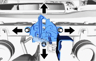
Loosen the 3 bolts.
-
Adjust the hood lock and tighten the 3 bolts.
- Torque:
- 7.5 N*m { 76 kgf*cm, 66 in.*lbf }
-
Check that the striker can engage the hood lock smoothly.
-
-
-
INSPECT FRONT DOOR
-
Check that the clearance measurements of areas a through h are within each standard range.
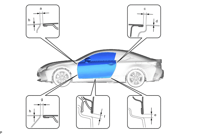
Standard Clearance Area Measurement Area Measurement a 2.3 to 5.3 mm (0.0906 to 0.209 in.) b -1.5 to 1.5 mm (-0.0591 to 0.0591 in.) c 2.3 to 5.3 mm (0.0906 to 0.209 in.) d -1.5 to 1.5 mm (-0.0591 to 0.0591 in.) e 3.65 to 6.65 mm (0.144 to 0.262 in.) f 3.65 to 6.65 mm (0.144 to 0.262 in.) g 2.3 to 5.3 mm (0.0906 to 0.209 in.) h -1.5 to 1.5 mm (-0.0591 to 0.0591 in.) Tech Tips
-
Use the same procedure for the RH side and LH side.
-
The following procedure is for the LH side.
-
Centering bolts are used to mount the door hinge to the vehicle body and door. The door cannot be adjusted with the centering bolts installed. Substitute the centering bolts with standard bolts when making adjustments.
-
-
-
ADJUST FRONT DOOR
Note
Make sure to turn the engine switch off when adjusting the door lock striker.
-
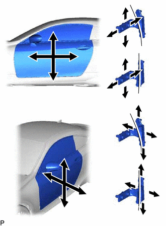
Using SST, loosen the 2 hinge bolts on the vehicle body and adjust the door position.
- SST
- 09812-00010
-
Tighten the 2 hinge bolts on the vehicle body after adjustment.
- Torque:
- 32.5 N*m { 331 kgf*cm, 24 ft.*lbf }
-
Loosen the 2 hinge bolts on the door and adjust the door position.
-
Loosen the 2 hinge bolts on the door and adjust the door position.
- Torque:
- 32.5 N*m { 331 kgf*cm, 24 ft.*lbf }
-
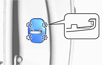
Disengage the 4 claws and remove the front door lock striker cover.
-
Using a T40 "TORX" socket wrench, slightly loosen the 2 striker mounting screws.
-
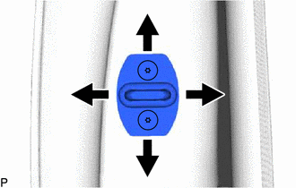
Using a brass bar and a hammer, hit the striker to adjust its position.
-
Using a T40 "TORX" socket wrench, tighten the 2 striker mounting screws after adjustment.
- Torque:
- 23 N*m { 235 kgf*cm, 17 ft.*lbf }
-
Engage the 4 claws to install the front door lock striker cover.
-
-
INSPECT LUGGAGE COMPARTMENT DOOR
-
Check that the clearance measurements of areas a through d are within each standard range.
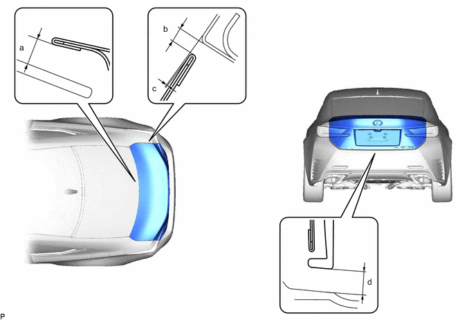
Standard Clearance Area Measurement Area Measurement a 7.85 mm (0.309 in.) b 2.0 to 5.0 mm (0.0787 to 0.197 in.) c -1.5 to 1.5 mm (-0.0591 to 0.0591 in.) d 7.2 mm (0.283 in.) Tech Tips
Centering bolts are used to mount the door hinge to the door. The door cannot be adjusted with the centering bolts installed. Substitute the centering bolts with standard bolts when making adjustments.
-
-
ADJUST LUGGAGE COMPARTMENT DOOR
-
Loosen the 4 door side hinge bolts to adjust the door horizontally and vertically.
-
Tighten the 4 bolts after adjustment.
- Torque:
- 8.0 N*m { 82 kgf*cm, 71 in.*lbf }
-
Using a T40 "TORX" socket wrench, slightly loosen the 2 striker mounting screws.
-
Using a brass bar and a hammer, hit the striker to adjust its position.
-
Using a T40 "TORX" socket wrench, tighten the 2 striker mounting screws after adjustment.
- Torque:
- 23 N*m { 235 kgf*cm, 17 ft.*lbf }
-