MULTI-MODE MANUAL TRANSAXLE SYSTEM IG Signal Circuit
| DTC Code | DTC Name |
|---|---|
| IG Signal Circuit |
DESCRIPTION
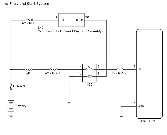
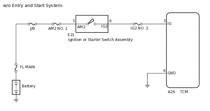
When the ignition switch is turned to ON, the battery voltage is applied to terminal IG of the TCM. Power is supplied to the TCM via terminals +B and IG.The TCM interprets the ignition switch condition through the potential at the IG terminal.
WIRING DIAGRAM
CAUTION / NOTICE / HINT
Inspect the fuses for circuits related to this system before performing the following procedure.
PROCEDURE
READ VALUE USING GTS (IGNITION SIGNAL)
Connect the GTS to the DLC3.
Turn the ignition switch to ON.
Turn the GTS on.
Enter the following menus: Powertrain / Multi-Mode M/T / Data List / Ignition Signal.
Read the Data List according to the display on the GTS.
Powertrain > Multi-Mode M/T > Data List
Tester Display
Measurement Item
Range
Normal Condition
Diagnostic Note
Ignition Signal
Ignition switch signal
OFF or ON
ON: Ignition switch ON
-
Powertrain > Multi-Mode M/T > Data List
Tester Display
Ignition Signal
OK
ON is displayed for the Data List item Ignition Signal when the ignition switch is turned to ON.
Result
Proceed to
OK
NG
CHECK HARNESS AND CONNECTOR (TCM - BODY GROUND)
-
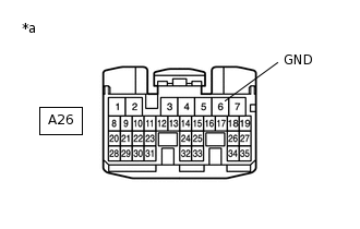
*a
Front view of wire harness connector
(to TCM)
Disconnect the TCM connector.
Measure the resistance according to the value(s) in the table below.
Standard Resistance
Tester Connection
Condition
Specified Condition
A26-6 (GND) - Body ground
Always
Below 1 Ω
Result
Proceed to
OK
NG
NG REPAIR OR REPLACE HARNESS OR CONNECTOR
-
INSPECT TCM (IG TERMINAL VOLTAGE)
-
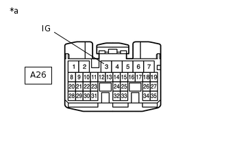
*a
Front view of wire harness connector
(to TCM)
Disconnect the TCM connector.
Turn the ignition switch to ON.
Measure the voltage according to the value(s) in the table below.
Standard Voltage
Tester Connection
Condition
Specified Condition
A26-3 (IG) - Body ground
Ignition switch off
Below 1 V
Ignition switch ON
11 to 14 V
Result
Result
Proceed to
OK
A
NG (w/ Entry and Start System)
B
NG (w/o Entry and Start System)
C
C INSPECT IGNITION OR STARTER SWITCH ASSEMBLYClick here
-
CHECK HARNESS AND CONNECTOR (IG2 RELAY - CERTIFICATION ECU)
Remove the IG2 relay from the center relay block.
Measure the voltage according to the value(s) in the table below.
Standard Voltage
Tester Connection
Condition
Specified Condition
IG2 relay terminal 2 - Body ground
Ignition switch off
Below 1 V
Ignition switch ON
11 to 14 V
Result
Proceed to
OK
NG
NG CHECK HARNESS AND CONNECTOR (CERTIFICATION ECU - IG2 RELAY)Click here
CHECK HARNESS AND CONNECTOR (IG2 RELAY - BODY GROUND)
Measure the resistance according to the value(s) in the table below.
Standard Resistance
Tester Connection
Condition
Specified Condition
IG2 relay terminal 1 - Body ground
Always
Below 1 Ω
Result
Proceed to
OK
NG
NG REPAIR OR REPLACE HARNESS OR CONNECTOR
CHECK HARNESS AND CONNECTOR (IG2 RELAY - BATTERY)
Measure the voltage according to the value(s) in the table below.
Standard Voltage
Tester Connection
Condition
Specified Condition
IG2 relay terminal 3 - Body ground
Always
11 to 14 V
Result
Proceed to
OK
NG
NG REPAIR OR REPLACE HARNESS OR CONNECTOR
INSPECT RELAY (IG2 RELAY)
Inspect the IG2 relay.
Result
Proceed to
OK
NG
OK REPAIR OR REPLACE HARNESS OR CONNECTOR (IG2 RELAY - TCM)
NG REPLACE RELAY (IG2 RELAY)
CHECK HARNESS AND CONNECTOR (CERTIFICATION ECU - IG2 RELAY)
Disconnect the certification ECU connector.
Measure the resistance according to the value(s) in the table below.
Standard Resistance
Tester Connection
Condition
Specified Condition
E49-20 (IG1D) - IG2 relay terminal 2
Always
Below 1 Ω
IG2 relay terminal 2 - Body ground
Always
10 kΩ or higher
Result
Proceed to
OK
NG
NG REPAIR OR REPLACE HARNESS OR CONNECTOR
INSPECT IGNITION OR STARTER SWITCH ASSEMBLY
Inspect the ignition or starter switch assembly.
Result
Proceed to
OK
NG
CHECK HARNESS AND CONNECTOR (IGNITION OR STARTER SWITCH ASSEMBLY - BATTERY)
Disconnect the ignition or starter switch assembly connector.
Measure the voltage according to the value(s) in the table below.
Standard Voltage
Tester Connection
Condition
Specified Condition
E21-5 (AM2) - Body ground
Always
11 to 14 V
Result
Proceed to
OK
NG
OK REPAIR OR REPLACE HARNESS OR CONNECTOR (IGNITION OR STARTER SWITCH ASSEMBLY - TCM)
NG REPAIR OR REPLACE HARNESS OR CONNECTOR (BATTERY - IGNITION OR STARTER SWITCH ASSEMBLY)