FRONT DISC BRAKE PAD(for 6-Pot Caliper) INSTALLATION

CAUTION / NOTICE / HINT
Tech Tips
-
Use the same procedure for the RH and LH sides, except where indicated.
-
The following procedure is for the LH side.
PROCEDURE
-
INSTALL FRONT DISC BRAKE ANTI-SQUEAL SHIM
-
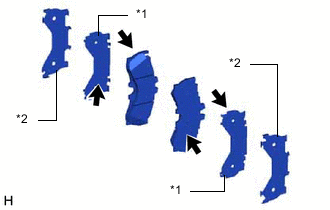
*1 No. 1 Anti-Squeal Shim *2 No. 2 Anti-Squeal Shim 
Disc Brake Grease Apply disc brake grease to the front disc brake pads and No. 1 anti-squeal shims at the positions shown in the illustration.
Note
-
Use the grease supplied with the anti-squeal shim kit or disc brake grease as the disc brake grease.
-
Keep the lining surface of the front disc brake pad free from grease.
-
Do not apply grease between the No. 1 and No. 2 anti-squeal shims.
-
-
Install the No. 1 and No. 2 anti-squeal shims to each of the front disc brake pads.
Note
When replacing the front disc brake pads with new ones, make sure to replace the front disc brake anti-squeal shim kit at the same time.
-
-
INSTALL PAD WEAR INDICATOR WIRE CLIP (for RH Side)
-
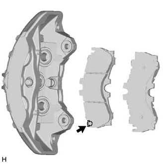
Install a new pad wear indicator wire clip to the interior side front disc brake pad.
Tech Tips
Install the pad wear indicator wire clip to the front disc brake pad RH side.
-
-
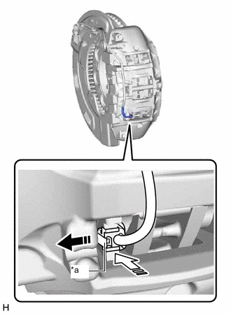
INSTALL FRONT DISC BRAKE PAD
-
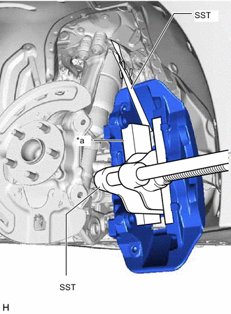
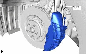
*a Wooden Block Using SST and a wooden block, push back the front disc brake pistons.
- SST
- 09719-77020
CAUTION:
Be careful not to get pinched by the disc brake cylinder assembly or other parts when installing the front disc brake pads.
Note
-
Make sure the brake fluid does not overflow from the reservoir.
-
Do not forcibly push in the front disc brake pistons.
-
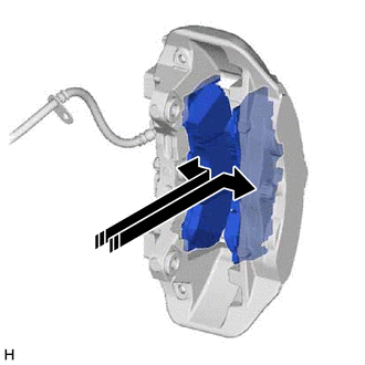
Install the 2 front disc brake pads to the disc brake cylinder assembly LH.
Note
When replacing the front disc brake pads with new ones, make sure to replace the pad wear indicator wire assembly and pad wear indicator clip at the same time.
-
-
INSTALL DISC BRAKE CYLINDER ASSEMBLY LH
-
Install the front disc LH.
-
Temporarily install the 5 hub nuts to the front axle hub LH to secure the front disc LH.
Note
Do not apply excessive force to the flexible hose.
-
Temporarily install the disc brake cylinder assembly LH with the bolt on the lower side of the disc brake cylinder assembly LH.
-
Remove the SST.
-
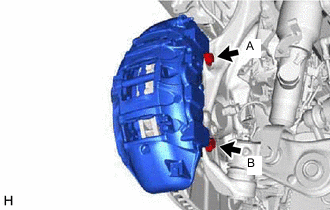
Install the disc brake cylinder assembly LH with the bolt (A) and bolt (B).
- Torque:
- 135 N*m { 1377 kgf*cm, 100 ft.*lbf }
-
for 2WD:
-
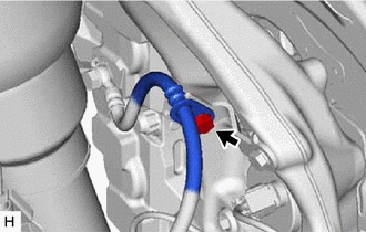
Install the flexible hose to the front flexible hose bracket LH with the bolt.
- Torque:
- 20 N*m { 204 kgf*cm, 15 ft.*lbf }
-
-
for AWD:
-
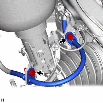
Install the flexible hose to the front flexible hose bracket LH and No. 2 front flexible hose bracket LH with the 2 bolts.
- Torque:
- 20 N*m { 204 kgf*cm, 15 ft.*lbf }
-
-
-
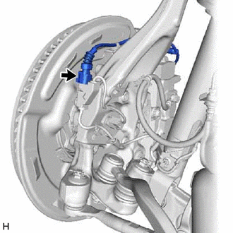
INSTALL FRONT PAD WEAR INDICATOR WIRE ASSEMBLY RH (for RH Side)
-
*a guide 
Install in this Direction (1) 
Install in this Direction (2) While pulling the pad wear indicator wire clip guide toward the inside of the vehicle, install the pad wear indicator wire assembly to the rear disc brake pad.
Note
The pad wear indicator wire retainer may become deformed if excessive force is used to pull on it. Therefore, do not excessively pull on the guide.
-
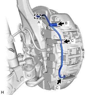
Attach the front pad wear indicator wire assembly RH to the 2 locations indicated in the illustration (C) in the disc brake cylinder assembly RH.
-
Attach the clamp (A) and install the bleeder plug cap (B).
-
Connect the front pad wear indicator wire connector to the front skid control sensor wire.
-
-
CONNECT BRAKE BOOSTER PUMP CONNECTOR (w/o Vacuum Brake Booster)
-
INSPECT AND ADJUST BRAKE FLUID LEVEL IN RESERVOIR (w/ Vacuum Brake Booster)
-
INSPECT AND ADJUST BRAKE FLUID LEVEL IN RESERVOIR (w/o Vacuum Brake Booster)
-
INSTALL FRONT WHEEL