POWER WINDOW CONTROL SYSTEM TERMINALS OF ECU
CHECK POWER WINDOW REGULATOR MASTER SWITCH ASSEMBLY
-
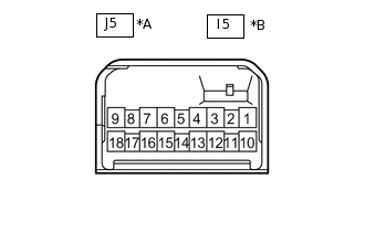
*A
for LHD
*B
for RHD
Disconnect the J5*1 or I5*2 power window regulator master switch assembly connector.
*1: for LHD
*2: for RHD
Measure the voltage and resistance according to the value(s) in the table below.
Tip:Measure the values on the wire harness side with the connector disconnected.
Table 1. for LHD Terminal No. (Symbol)
Wiring Color
Terminal Description
Condition
Specified Condition
J5-1 (E) - Body ground
W-B - Body ground
Ground
Always
Below 1 Ω
J5-6 (B) - J5-1 (E)
L - W-B
IG power supply
Power switch on (IG)
11 to 14 V
Power switch off
Below 1 V
Table 2. for RHD Terminal No. (Symbol)
Wiring Color
Terminal Description
Condition
Specified Condition
I5-9 (E) - Body ground
W-B - Body ground
Ground
Always
Below 1 Ω
I5-6 (B) - I5-9 (E)
L - W-B
IG power supply
Power switch on (IG)
11 to 14 V
Power switch off
Below 1 V
Reconnect the J5*1 or I5*2 power window regulator master switch assembly connector.
*1: for LHD
*2: for RHD
Measure the voltage according to the value(s) in the table below.
Table 3. for LHD Terminal No. (Symbol)
Wiring Color
Terminal Description
Condition
Specified Condition
J5-3 (LED) - J5-1 (E)
SB - W-B
LED illumination signal
Power switch on (IG)
11 to 14 V
Power switch off
Below 1 V
J5-4 (A) - J5-1 (E)
LG - W-B
Driver door power window motor AUTO UP output
Power switch on (IG), driver door power window fully open
11 to 14 V
Power switch on (IG), driver door power window switch up (AUTO UP position)
Below 1 V
Power switch on (IG), driver door power window fully closed
11 to 14 V
Driver door power window motor AUTO DOWN output
Power switch on (IG), driver door power window fully closed
11 to 14 V
Power switch on (IG), driver door power window switch down (AUTO DOWN position)
Below 1 V
Power switch on (IG), driver door power window fully open
11 to 14 V
J5-5 (D) - J5-1 (E)
W - W-B
Driver door power window motor DOWN output
Power switch on (IG), driver door power window switch off
Below 1 V
Power switch on (IG), driver door power window switch down (Manual operation)
11 to 14 V
J5-8 (U) - J5-1 (E)
P - W-B
Driver door power window motor UP output
Power switch on (IG), driver door power window switch off
Below 1 V
Power switch on (IG), driver door power window switch up (Manual operation)
11 to 14 V
J5-16 (U) - J5-1 (E)
G - W-B
Front passenger door power window motor UP output
Power switch on (IG), front passenger door power window switch off
Below 1 V
Power switch on (IG), front passenger door power window switch up (Manual operation)
11 to 14 V
J5-15 (D) - J5-1 (E)
BR - W-B
Front passenger door power window motor DOWN output
Power switch on (IG), front passenger door power window switch off
Below 1 V
Power switch on (IG), front passenger door power window switch down (Manual operation)
11 to 14 V
J5-12 (U) - J5-1 (E)
R - W-B
Rear door LH power window motor UP output
Power switch on (IG), rear door LH power window switch off
Below 1 V
Power switch on (IG), rear door LH power window switch up (Manual operation)
11 to 14 V
J5-13 (D) - J5-1 (E)
BE - W-B
Rear door LH power window motor DOWN output
Power switch on (IG), rear door LH power window switch off
Below 1 V
Power switch on (IG), rear door LH power window switch down (Manual operation)
11 to 14 V
J5-10 (U) - J5-1 (E)
G - W-B
Rear door RH power window motor UP output
Power switch on (IG), rear door RH power window switch off
Below 1 V
Power switch on (IG), rear door RH power window switch up (Manual operation)
11 to 14 V
J5-18 (D) - J5-1 (E)
BR - W-B
Rear door RH power window motor DOWN output
Power switch on (IG), rear door RH power window switch off
Below 1 V
Power switch on (IG), rear door RH power window switch down (Manual operation)
11 to 14 V
Table 4. for RHD Terminal No. (Symbol)
Wiring Color
Terminal Description
Condition
Specified Condition
I5-1 (U) - I5-9 (E)
W - W-B
Driver door power window motor UP output
Power switch on (IG), driver door power window switch off
11 to 14 V
Power switch on (IG), driver door power window switch up (Manual operation)
Below 1 V
J5-3 (LED) - J5-1 (E)
LG - W-B
LED illumination signal
Power switch on (IG)
11 to 14 V
Power switch off
Below 1 V
I5-4 (A) - I5-9 (E)
SB - W-B
Driver door power window motor AUTO UP output
Power switch on (IG), driver door power window fully open
11 to 14 V
Power switch on (IG), driver door power window switch up (AUTO UP position)
Below 1 V
Power switch on (IG), driver door power window fully closed
11 to 14 V
Driver door power window motor AUTO DOWN output
Power switch on (IG), driver door power window fully closed
11 to 14 V
Power switch on (IG), driver door power window switch down (AUTO DOWN position)
Below 1 V
Power switch on (IG), driver door power window fully open
11 to 14 V
I5-5 (D) - I5-9 (E)
B - W-B
Driver door power window motor DOWN output
Power switch on (IG), driver door power window switch off
Below 1 V
Power switch on (IG), driver door power window switch down (Manual operation)
11 to 14 V
I5-12 (U) - I5-9 (E)
V - W-B
Front passenger door power window motor UP output
Power switch on (IG), front passenger door power window switch off
Below 1 V
Power switch on (IG), front passenger door power window switch up (Manual operation)
11 to 14 V
I5-13 (D) - I5-9 (E)
Y - W-B
Front passenger door power window motor DOWN output
Power switch on (IG), front passenger door power window switch off
Below 1 V
Power switch on (IG), front passenger door power window switch down (Manual operation)
11 to 14 V
I5-18 (U) - I5-9 (E)
R - W-B
Rear door LH power window motor UP output
Power switch on (IG), rear door LH power window switch off
Below 1 V
Power switch on (IG), rear door LH power window switch up (Manual operation)
11 to 14 V
I5-10 (D) - I5-9 (E)
L - W-B
Rear door LH power window motor DOWN output
Power switch on (IG), rear door LH power window switch off
Below 1 V
Power switch on (IG), rear door LH power window switch down (Manual operation)
11 to 14 V
I5-16 (U) - I5-9 (E)
G - W-B
Rear door RH power window motor UP output
Power switch on (IG), rear door RH power window switch off
Below 1 V
Power switch on (IG), rear door RH power window switch up (Manual operation)
11 to 14 V
I5-15 (D) - I5-9 (E)
BR - W-B
Rear door RH power window motor DOWN output
Power switch on (IG), rear door RH power window switch off
Below 1 V
Power switch on (IG), rear door RH power window switch down (Manual operation)
11 to 14 V
-
CHECK POWER WINDOW REGULATOR SWITCH ASSEMBLY
-
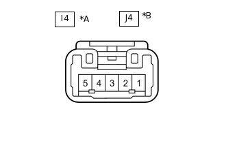
*A
for LHD
*B
for RHD
Disconnect the I4*1 or J4*2 power window regulator switch assembly connector.
*1: for LHD
*2: for RHD
Measure the voltage according to the value(s) in the table below.
Tip:Measure the values on the wire harness side with the connector disconnected.
Table 5. for LHD Terminal No. (Symbol)
Wiring Color
Terminal Description
Condition
Specified Condition
I4-3 (B) - Body ground
L - Body ground
IG power supply
Power switch on (IG)
11 to 14 V
Power switch off
Below 1 V
Table 6. for RHD Terminal No. (Symbol)
Wiring Color
Terminal Description
Condition
Specified Condition
J4-3 (B) - Body ground
L - Body ground
IG power supply
Power switch on (IG)
11 to 14 V
Power switch off
Below 1 V
Reconnect the I4*1 or J4*2 power window regulator switch assembly connector.
*1: for LHD
*2: for RHD
Measure the voltage according to the value(s) in the table below.
Table 7. for LHD Terminal No. (Symbol)
Wiring Color
Terminal Description
Condition
Specified Condition
I4-4 (U) - Body ground
Y - Body ground
Front passenger power window motor UP output
Power switch on (IG), power window regulator switch assembly off
Below 1 V
Power switch on (IG), power window regulator switch assembly up (Manual operation)
11 to 14 V
I4-1 (D) - Body ground
B - Body ground
Front passenger power window motor DOWN output
Power switch on (IG), power window regulator switch assembly off
Below 1 V
Power switch on (IG), power window regulator switch assembly down (Manual operation)
11 to 14 V
Table 8. for RHD Terminal No. (Symbol)
Wiring Color
Terminal Description
Condition
Specified Condition
J4-4 (U) - Body ground
R - Body ground
Front passenger power window motor UP output
Power switch on (IG), power window regulator switch assembly off
Below 1 V
Power switch on (IG), power window regulator switch assembly up (Manual operation)
11 to 14 V
J4-1 (D) - Body ground
GR - Body ground
Front passenger power window motor DOWN output
Power switch on (IG), power window regulator switch assembly off
Below 1 V
Power switch on (IG), power window regulator switch assembly down (Manual operation)
11 to 14 V
-
CHECK REAR POWER WINDOW REGULATOR SWITCH ASSEMBLY LH
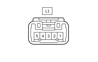
Disconnect the L1 rear power window regulator switch assembly LH connector.
Measure the voltage according to the value(s) in the table below.
Tip:Measure the values on the wire harness side with the connector disconnected.
Terminal No. (Symbol)
Wiring Color
Terminal Description
Condition
Specified Condition
L1-3 (B) - Body ground
P - Body ground
IG power supply
Power switch on (IG)
11 to 14 V
Power switch off
Below 1 V
Reconnect the L1 rear power window regulator switch assembly LH connector.
Measure the voltage according to the value(s) in the table below.
Terminal No. (Symbol)
Wiring Color
Terminal Description
Condition
Specified Condition
L1-4 (U) - Body ground
G - Body ground
Rear door LH power window motor UP output
Power switch on (IG), rear power window regulator switch assembly LH off
Below 1 V
Power switch on (IG), rear power window regulator switch assembly LH up (Manual operation)
11 to 14 V
L1-1 (D) - Body ground
Y - Body ground
Rear door LH power window motor DOWN output
Power switch on (IG), rear power window regulator switch assembly LH off
Below 1 V
Power switch on (IG), rear power window regulator switch assembly LH down (Manual operation)
11 to 14 V
CHECK REAR POWER WINDOW REGULATOR SWITCH ASSEMBLY RH
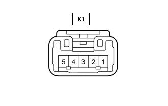
Disconnect the K1 rear power window regulator switch assembly RH connector.
Measure the voltage according to the value(s) in the table below.
Tip:Measure the values on the wire harness side with the connector disconnected.
Terminal No. (Symbol)
Wiring Color
Terminal Description
Condition
Specified Condition
K1-3 (B) - Body ground
L - Body ground
IG power supply
Power switch on (IG)
11 to 14 V
Power switch off
Below 1 V
Reconnect the K1 rear power window regulator switch assembly RH connector.
Measure the voltage according to the value(s) in the table below.
Terminal No. (Symbol)
Wiring Color
Terminal Description
Condition
Specified Condition
K1-4 (U) - Body ground
P - Body ground
Rear door RH power window motor UP output
Power switch on (IG), rear power window regulator switch assembly RH off
Below 1 V
Power switch on (IG), rear power window regulator switch assembly RH up (Manual operation)
11 to 14 V
K1-1 (D) - Body ground
W - Body ground
Rear door RH power window motor DOWN output
Power switch on (IG), rear power window regulator switch assembly RH off
Below 1 V
Power switch on (IG), rear power window regulator switch assembly RH up (Manual operation)
11 to 14 V
CHECK FRONT POWER WINDOW REGULATOR MOTOR ASSEMBLY LH (for LHD)
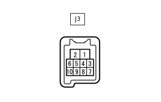
Disconnect the J3 front power window regulator motor assembly LH connector.
Measure the voltage and resistance according to the value(s) in the table below.
Tip:Measure the values on the wire harness side with the connector disconnected.
Terminal No. (Symbol)
Wiring Color
Terminal Description
Condition
Specified Condition
J3-1 (GND) - Body ground
W-B - Body ground
Ground
Always
Below 1 Ω
J3-2 (B) - Body ground
GR - Body ground
IG power supply
Always
11 to 14 V
Reconnect the J3 front power window regulator motor assembly LH connector.
Measure the voltage according to the value(s) in the table below.
Terminal No. (Symbol)
Wiring Color
Terminal Description
Condition
Specified Condition
J3-4 (AUTO) - J3-1 (GND)
LG - W-B
Driver door power window motor AUTO UP input
Power switch on (IG), driver door power window fully open
11 to 14 V
Power switch on (IG), driver door power window moving, power window regulator master switch assembly (driver door power window regulator switch) fully pulled up (Auto operation)
Below 1 V
Power switch on (IG), driver door power window fully closed
11 to 14 V
Driver door power window motor AUTO DOWN input
Power switch on (IG), driver door power window fully closed
11 to 14 V
Power switch on (IG), driver door power window moving, power window regulator master switch assembly (driver door power window regulator switch) fully pushed down (Auto operation)
Below 1 V
Power switch on (IG), driver door power window fully open
11 to 14 V
J3-5 (LED) - J3-1 (GND)
SB - W-B
LED illumination signal
Power switch on (IG)
11 to 14 V
Power switch off
Below 1 V
J3-7 (DOWN) - J3-1 (GND)
W - W-B
Driver door power window motor DOWN input
Power switch on (IG), power window regulator master switch assembly not pushed or pulled
11 to 14 V
Power switch on (IG), power window regulator master switch assembly (driver door power window regulator switch) pushed halfway down (Manual operation)
Below 1 V
Power switch on (IG), driver door power window fully closed
11 to 14 V
Power switch on (IG), power window regulator master switch assembly (driver door power window regulator switch) fully pushed down (Auto operation)
Below 1 V
Power switch on (IG), driver door power window fully open
11 to 14 V
J3-10 (UP) - J3-1 (GND)
P - W-B
Driver door power window motor UP input
Power switch on (IG), power window regulator master switch assembly (driver door power window regulator switch) not pushed or pulled
11 to 14 V
Power switch on (IG), power window regulator master switch assembly (driver door power window regulator switch) pulled halfway up (Manual operation)
Below 1 V
Power switch on (IG), driver door power window fully open
11 to 14 V
Power switch on (IG), power window regulator master switch assembly (driver door power window regulator switch) fully pulled up (Auto operation)
Below 1 V
Power switch on (IG), driver door power window fully closed
11 to 14 V
CHECK FRONT POWER WINDOW REGULATOR MOTOR ASSEMBLY RH (for RHD)
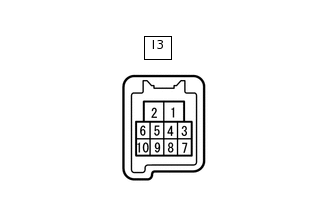
Disconnect the I3 front power window regulator motor assembly RH connector.
Measure the voltage and resistance according to the value(s) in the table below.
Tip:Measure the values on the wire harness side with the connector disconnected.
Terminal No. (Symbol)
Wiring Color
Terminal Description
Condition
Specified Condition
I3-1 (GND) - Body ground
W-B - Body ground
Ground
Always
Below 1 Ω
I3-2 (B) - Body ground
GR - Body ground
IG power supply
Always
11 to 14 V
Reconnect the I3 front power window regulator motor assembly RH connector.
Measure the voltage according to the value(s) in the table below.
Terminal No. (Symbol)
Wiring Color
Terminal Description
Condition
Specified Condition
I3-4 (AUTO) - I3-1 (GND)
SB - W-B
Driver door power window motor AUTO UP input
Power switch on (IG), driver door power window fully open
11 to 14 V
Power switch on (IG), driver door power window moving, power window regulator master switch assembly (driver door power window regulator switch) fully pulled up (Auto operation)
Below 1 V
Power switch on (IG), driver door power window fully closed
11 to 14 V
I3-4 (AUTO) - I3-1 (GND)
SB - W-B
Driver door power window motor AUTO DOWN input
Power switch on (IG), driver door power window fully closed
11 to 14 V
Power switch on (IG), driver door power window moving, power window regulator master switch assembly (driver door power window regulator switch) fully pushed down (Auto operation)
Below 1 V
Power switch on (IG), driver door power window fully open
11 to 14 V
I3-5 (LED) - I3-1 (GND)
LG - W-B
LED illumination signal
Power switch on (IG)
11 to 14 V
Power switch off
Below 1 V
I3-7 (DOWN) - I3-1 (GND)
B - W-B
Driver door power window motor DOWN input
Power switch on (IG), power window regulator master switch assembly (driver door power window regulator switch) not pushed or pulled
11 to 14 V
Power switch on (IG), power window regulator master switch assembly (driver door power window regulator switch) pushed halfway down (Manual operation)
Below 1 V
Power switch on (IG), driver door power window fully closed
11 to 14 V
Power switch on (IG), power window regulator master switch assembly (driver door power window regulator switch) fully pushed down (Auto operation)
Below 1 V
Power switch on (IG), driver door power window fully open
11 to 14 V
I3-10 (UP) - I3-1 (GND)
W - W-B
Driver door power window motor UP input
Power switch on (IG), power window regulator master switch assembly (driver door power window regulator switch) not pushed or pulled
11 to 14 V
Power switch on (IG), power window regulator master switch assembly (driver door power window regulator switch) pulled halfway up (Manual operation)
Below 1 V
Power switch on (IG), driver door power window fully open
11 to 14 V
Power switch on (IG), power window regulator master switch assembly (driver door power window regulator switch) fully pulled up (Auto operation)
Below 1 V
Power switch on (IG), driver door power window fully closed
11 to 14 V
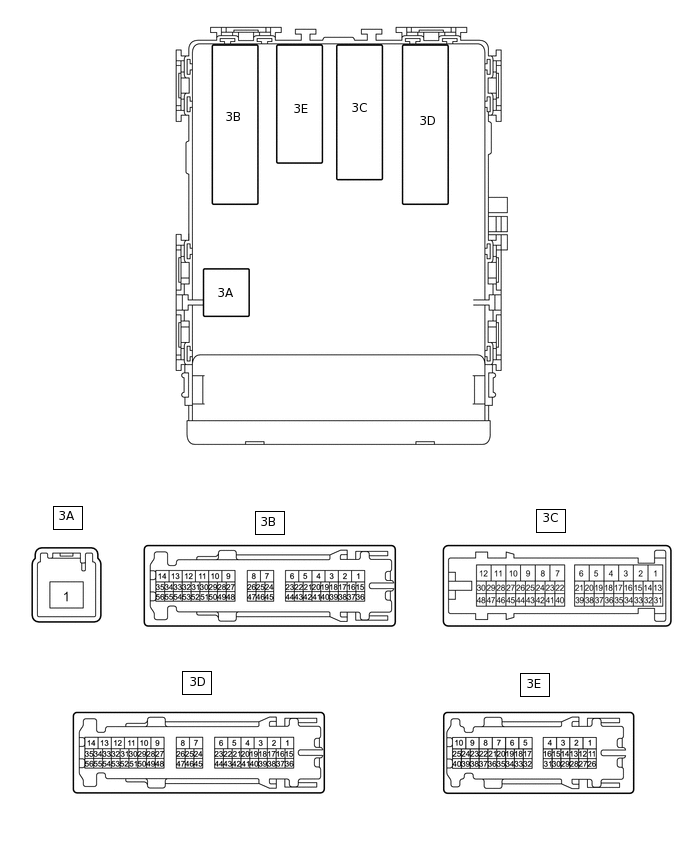
CHECK MAIN BODY ECU (MULTIPLEX NETWORK BODY ECU) AND INSTRUMENT PANEL JUNCTION BLOCK ASSEMBLY
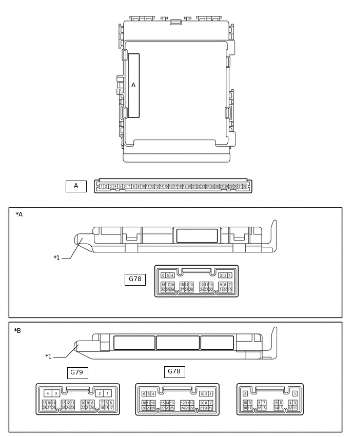
*A
Main Body ECU (Multiplex Network Body ECU) with 1 Connector
*B
Main Body ECU (Multiplex Network Body ECU) with 3 Connectors
*1
Main Body ECU (Multiplex Network Body ECU)
-
-
Remove the main body ECU (multiplex network body ECU).
for LHD:Click here
for RHD:Click here
Connect the instrument panel junction block assembly connectors.
Measure the voltage and resistance according to the value(s) in the table below.
Terminal No. (Symbol)
Wiring Color
Terminal Description
Condition
Specified Condition
A-11 (GND1) - Body ground
None - Body ground
Ground
Always
Below 1 Ω
A-30 (BECU) - Body ground
None - Body ground
Auxiliary battery power supply
Always
11 to 14 V
A-29 (ACC) - Body ground
None - Body ground
ACC power supply
Power switch on (ACC)
11 to 14 V
Power switch off
Below 1 V
A-32 (IG) - Body ground
None - Body ground
IG power supply
Power switch on (IG)
11 to 14 V
Power switch off
Below 1 V
Install the main body ECU (multiplex network body ECU).
for LHD:Click hereClick here
for RHD:Click hereClick here
Measure the voltage according to the value(s) in the table below.
Table 9. for LHD: Terminal No. (Symbol)
Wiring Color
Terminal Description
Condition
Specified Condition
G78-2 (KOFF) - Body ground
R - Body ground
Power window relay operation signal
Power switch on (IG)
11 to 14 V
Approximately 43 seconds after power switch off
Below 1 V
3E-32 (FLCY) - Body ground
W - Body ground
Front door courtesy switch LH input
Front door LH open
Below 1 V
Front door LH closed
Pulse generation
G78-19 (FRCY) - Body ground
L - Body ground
Front door courtesy switch RH input
Front door RH open
Below 1 V
Front door RH closed
Pulse generation
Table 10. for RHD: Terminal No. (Symbol)
Wiring Color
Terminal Description
Condition
Specified Condition
G78-2 (KOFF) - Body ground
R - Body ground
Power window relay operation signal
Power switch on (IG)
11 to 14 V
Approximately 43 seconds after power switch off
Below 1 V
3E-40 (FLCY) - Body ground
W - Body ground
Front door courtesy switch LH input
Front door LH open
Below 1 V
Front door LH closed
Pulse generation
G78-19 (FRCY) - Body ground
GR - Body ground
Front door courtesy switch RH input
Front door RH open
Below 1 V
Front door RH closed
Pulse generation