CRUISE CONTROL SYSTEM TERMINALS OF ECM
CHECK ECM (for 1UR-FE)

Disconnect the C30, G44 and G45 ECM connectors.
Measure the voltage and resistance according to the value(s) in the table below.
Terminal No. (Symbol)
Wiring Color
Terminal Description
Condition
Specified Condition
G44-24 (BATT) - Body ground
L - Body ground
Power source
Always
11 to 14 V
G45-21 (IGSW) - Body ground
W - Body ground
IG power source
Engine switch on (IG)
11 to 14 V
G45-21 (IGSW) - Body ground
W - Body ground
IG power source
Engine switch off
Below 1 V
G44-8 (ST1-) - Body ground
B - Body ground
Stop light switch signal
Engine switch on (IG), brake pedal released
11 to 14 V
G44-8 (ST1-) - Body ground
B - Body ground
Stop light switch signal
Engine switch on (IG), brake pedal depressed
Below 1 V
G45-18 (STP) - Body ground
V - Body ground
Stop light switch signal
Brake pedal depressed
11 to 14 V
G45-18 (STP) - Body ground
V - Body ground
Stop light switch signal
Brake pedal released
Below 1 V
G45-11 (CCS) - Body ground
B - Body ground
Cruise control switch
Cruise control switch on
Below 2.5 Ω
G45-11 (CCS) - Body ground
B - Body ground
Cruise control switch
Cruise control switch off
1 MΩ or higher
G45-11 (CCS) - Body ground
B - Body ground
Cruise control switch
+RES switch held on
235 to 245 Ω
G45-11 (CCS) - Body ground
B - Body ground
Cruise control switch
-SET switch held on
617 to 643 Ω
G45-11 (CCS) - Body ground
B - Body ground
Cruise control switch
CANCEL switch held on
1509 to 1571 Ω
C30-12 (E1) - Body ground
BR - Body ground
Ground
Always
Below 1 Ω
If the result is not as specified, there may be a malfunction on the wire harness side.
Reconnect the C30, G44 and G45 ECM connectors.
Measure the voltage according to the value(s) in the table below.
Terminal No. (Symbol)
Wiring Color
Terminal Description
Condition
Specified Condition
G45-24 (S) - Body ground
V - Body ground
Transmission control switch
Engine switch on (IG), shift lever in S
11 to 14 V
G45-24 (S) - Body ground
V - Body ground
Transmission control switch
Engine switch on (IG), shift lever not in S
Below 1 V
G45-16 (SFTU) - Body ground
GR - Body ground
Transmission control switch
Engine switch on (IG), shift lever in S → shift lever moved to "+"
11 to 14 V → Below 1 V
G45-22 (SFTD) - Body ground
LG - Body ground
Transmission control switch
Engine switch on (IG), shift lever in S → shift lever moved to "-"
11 to 14 V → Below 1 V
C28-27 (D) - Body ground
B - Body ground
Park/neutral position switch signal
Engine switch on (IG), shift lever in D
11 to 14 V
C28-27 (D) - Body ground
B - Body ground
Park/neutral position switch signal
Engine switch on (IG), shift lever not in D
Below 1 V
C28-35 (P) - Body ground
L - Body ground
Park/neutral position switch signal
Engine switch on (IG), shift lever in P
11 to 14 V
C28-35 (P) - Body ground
L - Body ground
Park/neutral position switch signal
Engine switch on (IG), shift lever not in P
Below 1 V
C28-28 (R) - Body ground
R - Body ground
Park/neutral position switch signal
Engine switch on (IG), shift lever in R
11 to 14 V
C28-28 (R) - Body ground
R - Body ground
Park/neutral position switch signal
Engine switch on (IG), shift lever not in R
Below 1 V
C28-29 (N) - Body ground
G - Body ground
Park/neutral position switch signal
Engine switch on (IG), shift lever in N
11 to 14 V
C28-29 (N) - Body ground
G - Body ground
Park/neutral position switch signal
Engine switch on (IG), shift lever not in N
Below 1 V
If the result is not as specified, the ECM may be malfunctioning.
CHECK ECM (for 1GR-FE)
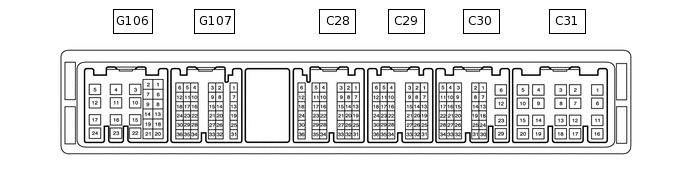
Disconnect the C30, G106 and G107 ECM connectors.
Measure the voltage and resistance according to the value(s) in the table below.
Terminal No. (Symbol)
Wiring Color
Terminal Description
Condition
Specified Condition
G106-24 (BATT) - Body ground
L - Body ground
Power source
Always
11 to 14 V
G107-21 (IGSW) - Body ground
W - Body ground
IG power source
Engine switch on (IG)
11 to 14 V
G107-21 (IGSW) - Body ground
W - Body ground
IG power source
Engine switch off
Below 1 V
G106-8 (ST1-) - Body ground
B - Body ground
Stop light switch signal
Engine switch on (IG), brake pedal released
11 to 14 V
G106-8 (ST1-) - Body ground
B - Body ground
Stop light switch signal
Engine switch on (IG), brake pedal depressed
Below 1 V
G107-18 (STP) - Body ground
V - Body ground
Stop light switch signal
Brake pedal depressed
11 to 14 V
G107-18 (STP) - Body ground
V - Body ground
Stop light switch signal
Brake pedal released
Below 1 V
G107-11 (CCS) - Body ground
B - Body ground
Cruise control switch
Cruise control switch on
Below 2.5 Ω
G107-11 (CCS) - Body ground
B - Body ground
Cruise control switch
Cruise control switch off
1 MΩ or higher
G107-11 (CCS) - Body ground
B - Body ground
Cruise control switch
+RES switch held on
235 to 245 Ω
G107-11 (CCS) - Body ground
B - Body ground
Cruise control switch
-SET switch held on
617 to 643 Ω
G107-11 (CCS) - Body ground
B - Body ground
Cruise control switch
CANCEL switch held on
1509 to 1571 Ω
C30-12 (E1) - Body ground
BR - Body ground
Ground
Always
Below 1 Ω
If the result is not as specified, there may be a malfunction on the wire harness side.
Reconnect the C30, G106 and G107 ECM connectors.
Measure the voltage according to the value(s) in the table below.
Terminal No. (Symbol)
Wiring Color
Terminal Description
Condition
Specified Condition
G107-24 (S) - Body ground
V - Body ground
Transmission control switch
Engine switch on (IG), shift lever in S
11 to 14 V
G107-24 (S) - Body ground
V - Body ground
Transmission control switch
Engine switch on (IG), shift lever not in S
Below 1 V
G107-16 (SFTU) - Body ground
GR - Body ground
Transmission control switch
Engine switch on (IG), shift lever in S → shift lever moved to "+"
11 to 14 V → Below 1 V
G107-22 (SFTD) - Body ground
LG - Body ground
Transmission control switch
Engine switch on (IG), shift lever in S → shift lever moved to "-"
11 to 14 V → Below 1 V
C28-27 (D) - Body ground
B - Body ground
Park/neutral position switch signal
Engine switch on (IG), shift lever in D
11 to 14 V
C28-27 (D) - Body ground
B - Body ground
Park/neutral position switch signal
Engine switch on (IG), shift lever not in D
Below 1 V
C28-35 (P) - Body ground
L - Body ground
Park/neutral position switch signal
Engine switch on (IG), shift lever in P
11 to 14 V
C28-35 (P) - Body ground
L - Body ground
Park/neutral position switch signal
Engine switch on (IG), shift lever not in P
Below 1 V
C28-28 (R) - Body ground
R - Body ground
Park/neutral position switch signal
Engine switch on (IG), shift lever in R
11 to 14 V
C28-28 (R) - Body ground
R - Body ground
Park/neutral position switch signal
Engine switch on (IG), shift lever not in R
Below 1 V
C28-29 (N) - Body ground
G - Body ground
Park/neutral position switch signal
Engine switch on (IG), shift lever in N
11 to 14 V
C28-29 (N) - Body ground
G - Body ground
Park/neutral position switch signal
Engine switch on (IG), shift lever not in N
Below 1 V
If the result is not as specified, the ECM may be malfunctioning.