STEERING LOCK SYSTEM, Diagnostic DTC:B2782
| DTC Code | DTC Name |
|---|---|
| B2782 | Power Source Control ECU Malfunction |
DESCRIPTION
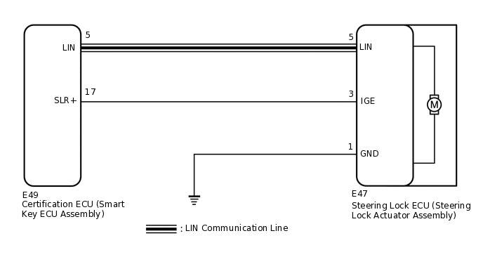
The certification ECU (smart key ECU assembly) has a power source mode switching function.
This DTC is stored when the IGE input (the steering lock motor activation permission signal) sent directly from the certification ECU (smart key ECU assembly) to the steering lock ECU (steering lock actuator assembly) is determined to be abnormal.
The steering lock ECU (steering lock actuator assembly) is not connected to the CAN communication system. However, the steering lock ECU (steering lock actuator assembly) is connected to the certification ECU (smart key ECU assembly) via LIN communication and communicates with other components via CAN communication through the certification ECU (smart key ECU assembly).
DTC No. |
Detection Item |
DTC Detection Condition |
Trouble Area |
Note |
|---|---|---|---|---|
B2782 |
Power Source Control ECU Malfunction |
Either of the following conditions is met (1-trip detection logic (Only output while a malfunction is present and the engine switch is on (IG).)):
Tip:
If the power supply signal from the LIN communication line does not match the power supply signal from the direct line, the system is determined to be malfunctioning. |
|
DTC Output Confirmation Operation: Perform a steering lock/unlock operation. (The steering locks when a door is opened with the shift lever in N (for Multi-Mode Manual Transaxle) and the engine switch off. The steering unlocks when the engine switch is turned on (ACC) or on (IG) while carrying the key.) |
Vehicle Condition when Malfunction Detected |
Fail-safe Function when Malfunction Detected |
|---|---|
The steering cannot be locked or unlocked. For this reason, the engine cannot be started. |
Prohibits the engine from being started (the engine does not crank). |
DTC No. |
Data List Item |
Active Test Item |
|---|---|---|
B2782 |
|
- |
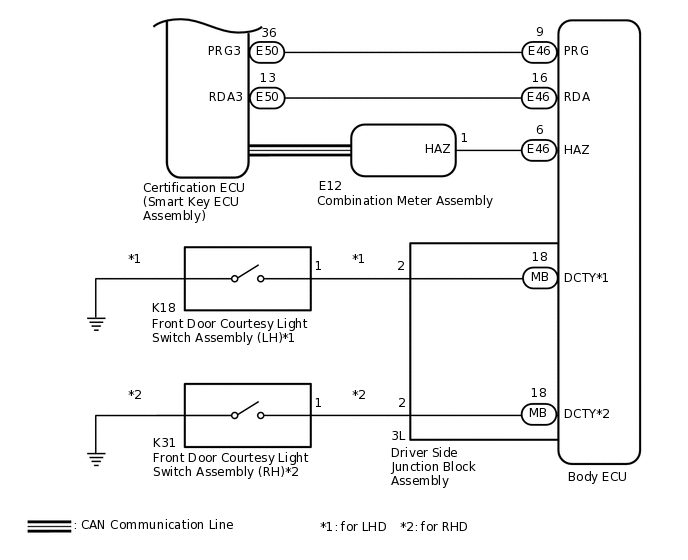
WIRING DIAGRAM
CAUTION / NOTICE / HINT
When using the GTS with the engine switch off, connect the GTS to the vehicle and turn a courtesy light switch on and off at intervals of 1.5 seconds or less until communication between the GTS and the vehicle begins. Then select Model Code "KEY REGIST" under manual mode and enter the following menus: Body Electrical / Entry&Start(CAN). While using the GTS, periodically turn a courtesy light switch on and off at intervals of 1.5 seconds or less to maintain communication between the GTS and the vehicle.
The steering lock system uses LIN communication. First perform the inspections in "How to Proceed with Troubleshooting" to confirm that there are no communication malfunctions before proceeding with troubleshooting.
When disconnecting the cable from the negative (-) battery terminal, some systems need to be initialized after the cable is reconnected.
After performing repairs, perform the DTC output confirmation operation, and then confirm that no DTCs are output again.
When replacing the steering lock ECU (steering lock actuator assembly) or certification ECU (smart key ECU assembly), registration must be performed (refer to Service Bulletin).
PROCEDURE
INSPECT STEERING LOCK ECU (STEERING LOCK ACTUATOR ASSEMBLY) (MOTOR ACTIVATION COMMAND SIGNAL)
Make sure that there is no looseness at the locking part and the connecting part of the connector.
Disconnect the E47 steering lock ECU (steering lock actuator assembly) connector.
-
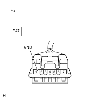
*a
Front view of wire harness connector
(to Steering Lock ECU (Steering Lock Actuator Assembly))
Measure the resistance according to the value(s) in the table below.
Standard Resistance
Tester Connection
Condition
Specified Condition
E47-1 (GND) - Body ground
Always
Below 1 Ω
Reconnect the E47 steering lock ECU (steering lock actuator assembly) connector.
Move the shift lever to N* and turn the engine switch off.
*: for Multi-Mode Manual Transaxle
-
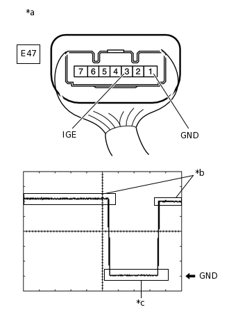
*a
Component with harness connected
(Steering Lock ECU (Steering Lock Actuator Assembly))
*b
Steering Lock Motor not Operating
*c
Steering Lock Motor Operating
Check the signal waveform according to the condition(s) in the table below.
Standard Frequency
Item
Content
Tester Connection
E47-3 (IGE) - E47-1 (GND)
Tool Setting
2 V/DIV., 200 ms./DIV.
Vehicle Condition
Steering lock motor not operating → Operating → Not operating
Tip:When taking measurements when the lock motor is stopped, it is not necessary to perform any operations.
In order to take measurements when the lock motor is operating, perform either of the following operations:
-
To unlock the steering, carry the key and turn the engine switch on (ACC) or on (IG).
To lock the steering, turn the engine switch off with the shift lever in N*, and then open a door.
-
*: for Multi-Mode Manual Transaxle
Result
Proceed to
OK
NG
NG CHECK HARNESS AND CONNECTOR (STEERING LOCK ECU (STEERING LOCK ACTUATOR ASSEMBLY) - CERTIFICATION ECU (SMART KEY ECU ASSEMBLY))Click here
CLEAR DTC AND DATA LIST MALFUNCTION RECORD
Clear the DTCs.
Body Electrical > Entry&Start > Clear DTCs
Disconnect the cable from the negative (-) battery terminal, wait for 30 seconds or more, and then reconnect the cable to the negative (-) battery terminal to clear the record of malfunctions stored in the Data List.
CAUTION:After turning the engine switch off, waiting time may be required before disconnecting the cable from the battery terminal. Therefore, make sure to read the disconnecting the cable from the battery terminal notices before proceeding with work.
Result
Proceed to
NEXT
READ VALUE USING GTS (POWER SUPPLY SHORT)
Perform the DTC output confirmation operation.
Check if DTC B2782 is output.
Body Electrical > Entry&Start > Trouble Codes
Use the Data List to check if the steering lock control is functioning properly.
Body Electrical > Entry&Start > Data List
Tester Display
Measurement Item
Range
Normal Condition
Diagnostic Note
Power Supply Short
Record of malfunction of signal sent to steering lock motor (steering lock actuator assembly) from certification ECU (smart key ECU assembly) (short circuit)
(DTC B2782 is output)
OK or NG(Past)
OK: No record of malfunction (short circuit)
NG(Past): Record of malfunction (short circuit) exists
This item records malfunctions in the circuit between the certification ECU (smart key ECU assembly) and steering lock motor (steering lock actuator assembly).
Body Electrical > Entry&Start > Data List
Tester Display
Power Supply Short
Result
Result
Proceed to
DTC B2782 is not output.
"OK" is displayed on the GTS.
A
DTC B2782 is output.
"NG(Past)" is displayed on the GTS.
B
A SYSTEM RETURNED TO NORMAL (DTC STORED DUE TO BAD CONNECTION, BUT SYSTEM RETURNED TO NORMAL BY RECONNECTING CONNECTOR)
CHECK HARNESS AND CONNECTOR (STEERING LOCK ECU (STEERING LOCK ACTUATOR ASSEMBLY) - CERTIFICATION ECU (SMART KEY ECU ASSEMBLY))
Make sure that there is no looseness at the locking part and the connecting part of the connectors.
Disconnect the E47 steering lock ECU (steering lock actuator assembly) connector.
Disconnect the E49 certification ECU (smart key ECU assembly) connector.
Check for deformation and corrosion of the connector case and terminals.
OK
There is no deformation or corrosion of the connector case or terminals.
Measure the resistance according to the value(s) in the table below.
Standard Resistance
Tester Connection
Condition
Specified Condition
E47-3 (IGE) - E49-17 (SLR+)
Always
Below 1 Ω
E47-3 (IGE) or E49-17 (SLR+) - Body ground
Always
10 kΩ or higher
Result
Proceed to
OK
NG
OK REPLACE CERTIFICATION ECU (SMART KEY ECU ASSEMBLY)
NG REPAIR OR REPLACE HARNESS OR CONNECTOR