MANUAL TRANSMISSION SYSTEM
-
FUNCTION
-
Gear Shift Indicator System
-
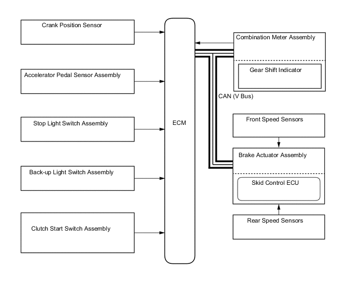
In the Gear Shift Indicator system, the ECM calculates a shift position for good environmental driving performance from the vehicle conditions and sends a request signal to the combination meter assembly to indicate "upshifting or downshifting". Then, the Gear Shift Indicator in the combination meter assembly displays the shift recommendation to the driver.
-
The ECM determines the actual gear position based on the signals from the speed sensors and crank position sensor, and the target gear position based on the signals from the accelerator pedal sensor assembly and speed sensors.
-
By driving in accordance with the shift change recommendations that are indicated by the Gear Shift Indicator, the driver can enhance environmental driving performance, improving fuel economy and reducing exhaust gas output within limits of engine performance.
Control of Gear Shift Indicator Control Outline Shifting Recommendation Control Calculates an environmentally favorable shift position based on the driving conditions of the vehicle, and gives shifting recommendation. Shift Control in Uphill Traveling Prevents unnecessary shifting instruction by estimating the gradient of the road based on the driving conditions. Provides shift position instructions that enable the vehicle to attain the proper drive force. Delta Throttle Accelerate Control Determines a deceleration request when the driver releases the accelerator pedal suddenly. Thus, it will not provide a shift-up instruction. However, it will provide a shift-up recommendation to protect the engine if the engine speed is high. -
The Gear Shift Indicator will not effect control while the vehicle is being driven in reverse.
-
The Gear Shift Indicator will not effect control while the vehicle is stopped or the clutch is not being engaged while shifting.
-
Upon receiving a shift instruction request from the ECM, the combination meter assembly will illuminate the indicator light.
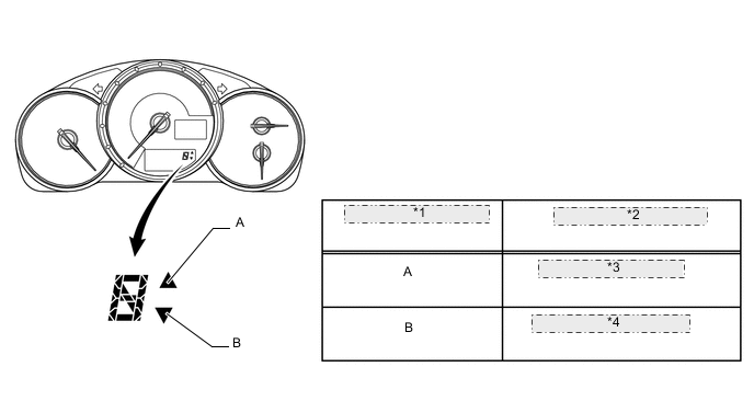
*1 Illumination Location *2 Instruction Description *3 Shift-up Recommendation *4 Shift-down Recommendation
-
-
-
CONSTRUCTION
-
Gear Train
-
The transmission synchromesh mechanism is an all-speed constant mesh type.
Gear 1st, 2nd and 3rd 4th, 5th, 6th and Reverse Synchromesh mechanism type Triple-cone Single-cone 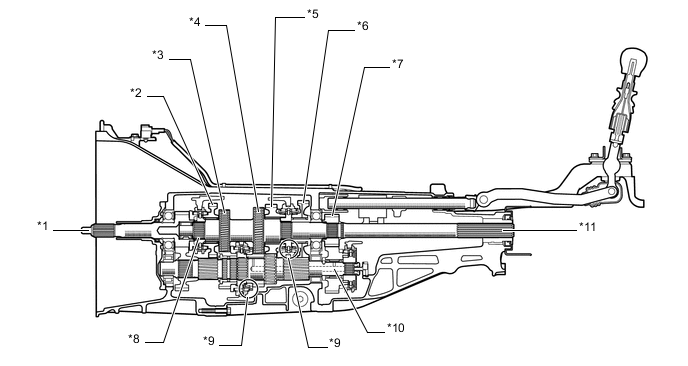
Text in Illustration *1 Input Shaft *2 Reverse Gear *3 4th Gear *4 3rd Gear *5 2nd Gear *6 1st Gear *7 6th Gear *8 5th Gear *9 Triple-cone Type Synchromesh Mechanism *10 Counter Shaft *11 Output Shaft - -
-
-
Shift Control Mechanism
-
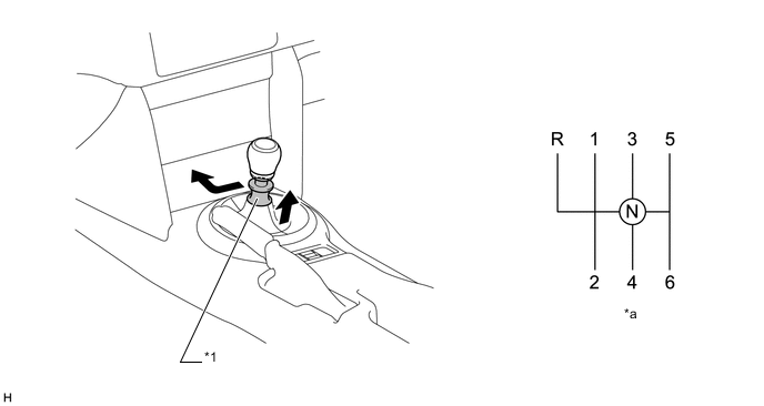
The shift control mechanism uses the semi-direct method to achieve short stroke and good rigidity.
-
Friction is lowered during operation by the adoption of slide ball bearings in the shift fork shaft support part, improving the feel of shifting while driving as well as when at a standstill.
-
Resin or leather gearshift lever knob is available according to specifications.
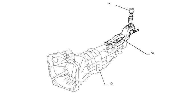
Text in Illustration *1 Shift Lever Knob *2 Manual Transmission Assembly *a Semi-Direct Mechanism - - -
The reverse miss shift prevention mechanism prevents shifting into reverse unless the shift lock release collar provided on the shift lever is raised.
-
A pull-collar gearshift lever has been adopted to prevent incorrect operation while in forward or in reverse.
Text in Illustration *1 Pull Collar - - *a Shift Pattern - - -
A stopper cover is provided on the 1st-2nd side, so that the pull collar must be pulled upward in order to shift into reverse. This reduces the amount of shift effort and ensures a precise shifting operation.
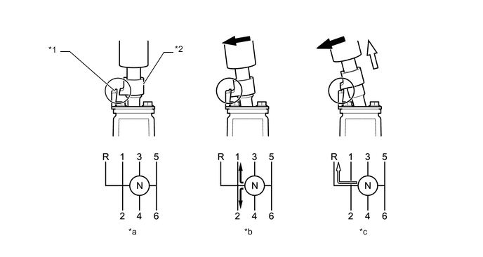
Text in Illustration *1 Stopper Cover *2 Pull Collar *a Neutral *b 1st/2nd *c Reverse - - 
Select Direction 
Pulled-Up
-
-
Shift and select mechanism
-
The shift mechanism has 4 shift forks, 5 shift fork shafts, and an interblock.
-
Friction is lowered during operation by the adoption of slide ball bearings in the shift fork shaft support part, improving the feel of shifting while driving as well as when at a standstill.
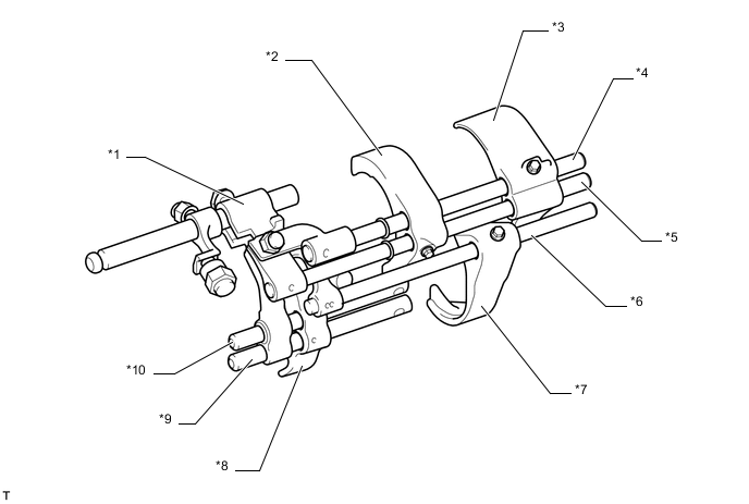
Text in Illustration *1 Interlock Block *2 1st-2nd Shift Fork *3 5th Reverse Shift Fork *4 Main Shift Fork Shaft *5 No. 2 Shift Fork Shaft *6 No. 3 Shift Fork Shaft *7 3rd-4th Shift Fork *8 6th Shift Fork *9 No. 5 Shift Fork Shaft *10 No. 4 Shift Fork Shaft -
Friction is lowered during operation by the adoption of slide ball bearings in the shift fork shaft support part.
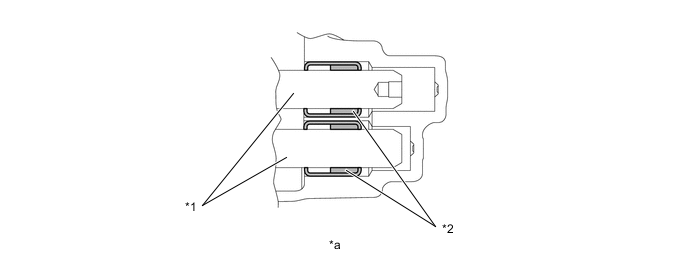
Text in Illustration *1 Shift Fork Shaft *2 Slide Ball Bearing *a Shift Fork Shaft Support Part - - -
All shift forks in the shift fork shaft slide mechanism are fastened to the shift fork shaft, and a system whereby the entire fork shaft slides has been adopted, reducing friction during operation.
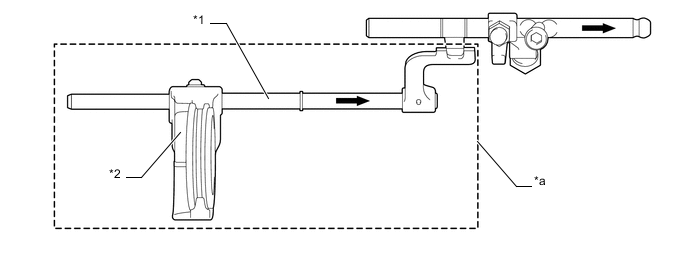
Text in Illustration *1 Shift Fork Shaft *2 Shift Fork *a The entire fork shaft slides smoothly. - - Slide - - -
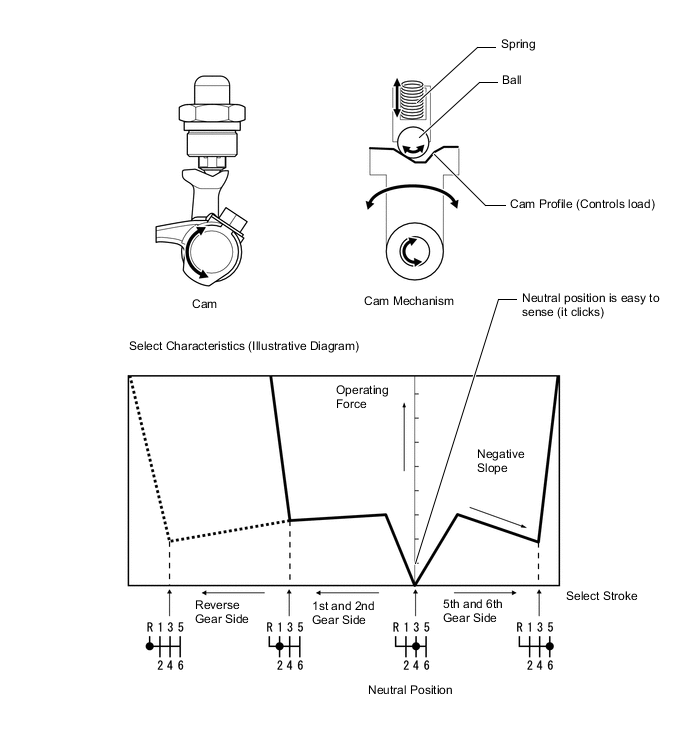
A ball plunger shift detent has been adopted for the shift detent mechanism, and a non-linear cam that enables quick select operation through negative slope characteristics and by clarifying the neutral gear position has been adopted.
-
-