TELEMATICS SYSTEM TERMINALS OF ECU
Tech Tips
Check from the rear of the connector while it is connected to the components.
-
TELEMATICS TRANSCEIVER
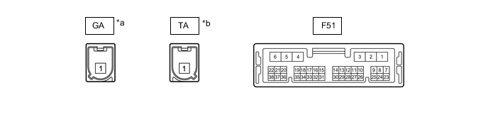
*a Connector Color: Gray (to GNSS Antenna) *b Connector Color: Blue (to Telephone Antenna) Terminal No. (Symbol) Wiring Color Terminal Description Condition Specified Condition F51-1 (+B) - F51-4 (E) W - W-B Power source (+B) Always 11 to 14 V F51-2 (SPI+) - F51-4 (E) BR - W-B*1
LA-LG - W-B*2
Sound signal Audio system playing A waveform synchronized with sound signals is output F51-3 (SPI-) - F51-4 (E) P - W-B*1
LA-L - W-B*2
Sound signal Audio system playing A waveform synchronized with sound signals is output F51-4 (E) - Body ground W-B - Body ground Ground Always Below 1 V F51-5 (SPO+) - F51-4 (E) Y - W-B*1
LA-LG - W-B*2
Sound signal Audio system playing, or emergency call mode A waveform synchronized with sound signals is output F51-6 (SPO-) - F51-4 (E) B - W-B*1
LA-L - W-B*2
Sound signal Audio system playing, or emergency call mode A waveform synchronized with sound signals is output F51-7 (IG2) - F51-4 (E) B - W-B Power source (IG) Ignition switch ON 11 to 14 V Ignition switch off Below 1 V F51-8 (ACC) - F51-4 (E) GR - W-B Power source (ACC) Ignition switch ACC 11 to 14 V Ignition switch off Below 1 V F51-9 (SLED) - F51-4 (E) LG - W-B Manual (SOS) switch illumination power supply Ignition switch ACC 11 to 14 V Ignition switch off Below 1 V F51-10 (SPDP) - F51-4 (E) V - W-B Vehicle speed signal for Radio and Display Type:
See "Vehicle Signal Check Mode" in Operation Check
w/o Navigation System: Click here
w/ Navigation System:
- for Radio Receiver Type:
Vehicle being driven at approx. 5 km/h (3 mph)
Pulse generation
(See waveform 1)
F51-11 (IND1) - F51-4 (E) B - W-B Manual (SOS) switch indicator (red) illumination signal For 10 seconds after ignition switch turned to ON
(Indicator (red) illuminated)
1 to 8.5 V Ignition switch off
(Indicator (red) not illuminated)
Below 1 V F51-12 (IND2) - F51-4 (E) BE - W-B Manual (SOS) switch indicator (green) illumination signal For 12 seconds after ignition switch turned to ON
(Indicator (green) illuminated)
1 to 8.5 V Ignition switch off
(Indicator (green) not illuminated)
Below 1 V F51-15 (CANP) GR CAN communication signal - - F51-16 (CANN) LG CAN communication signal - - F51-17 (MUTE) - F51-4 (E) L - W-B Mute signal Audio system playing 3.5 V or higher Emergency call mode Below 1 V F51-18 (MCO+) - F51-4 (E) G - W-B Sent microphone voice signal for Radio and Display Type:
See "Microphone Check" in Operation Check
w/o Navigation System: Click here
w/ Navigation System:
- for Radio Receiver Type:
"Bluetooth" hands-free voice signal received
A waveform synchronized with sound signals is output F51-19 (MCO-) - F51-4 (E) R - W-B Sent microphone voice signal for Radio and Display Type:
See "Microphone Check" in Operation Check
w/o Navigation System: Click here
w/ Navigation System:
- for Radio Receiver Type:
"Bluetooth" hands-free voice signal received
A waveform synchronized with sound signals is output F51-19 (ILL+) - F51-4 (E) G - W-B Illumination signal Light control switch off Below 1 V Light control switch in tail or head position 11 to 14 V F51-24 (GSW) - F51-4 (E) W - W-B Collision detection signal Ignition switch ON Pulse generation
(Refer to waveform 2)
F51-26 (SIG-) - F51-4 (E) SB - W-B Ground Always Below 1 V F51-27 (SIG1) - F51-4 (E) L - W-B Manual (SOS) switch condition signal Manual (SOS) switch not pressed 1.5 to 2.0 V Manual (SOS) switch pressed 0.5 to 0.8 V F51-32 (SGND) - F51-4 (E) Shield - W-B Shield ground Always Below 1 V F51-33 (MCVD) - F51-4 (E) B - W-B Microphone power supply Ignition switch off Below 1 V Ignition switch ACC 4 to 6 V F51-34 (MCI+) - F51-4 (E) W - W-B Receive microphone voice signal for Radio and Display Type:
See "Microphone Check" in Operation Check
w/o Navigation System: Click here
w/ Navigation System:
- for Radio Receiver Type:
"Bluetooth" hands-free voice signal received
A waveform synchronized with sound signals is output F51-35 (MCI-) - F51-4 (E) R - W-B Receive microphone voice signal for Radio and Display Type:
See "Microphone Check" in Operation Check
w/o Navigation System: Click here
w/ Navigation System:
- for Radio Receiver Type:
"Bluetooth" hands-free voice signal received
A waveform synchronized with sound signals is output
-
*1: w/ Navigation System
-
*2: w/o Navigation System
-
Oscilloscope waveform:
-
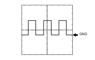
Waveform 1
Item Content Tester Connection F51-10 (SPDP) - F51-4 (E) Tool Setting 5 V/DIV., 200 ms./DIV. Condition Vehicle being driven at approx. 5 km/h (3 mph) Tech Tips
The wavelength becomes shorter as the vehicle speed increases.
-
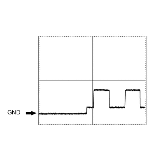
Waveform 2
Item Condition Tester Connection F51-24 (GSW) - F51-4 (E) Tool setting 5.0 V/DIV., 20 ms./DIV. Vehicle condition Ignition switch ON
-
-
-
RADIO RECEIVER ASSEMBLY (for Radio Receiver Type)
-
RADIO AND DISPLAY RECEIVER ASSEMBLY (for Radio and Display Type)
-
w/o Navigation System:
-
w/ Navigation System:
-