FRONT WIPER MOTOR INSTALLATION
PROCEDURE
INSTALL WIPER MOTOR WIRE
Attach the claw to install the wiper motor wire.
INSTALL WINDSHIELD WIPER MOTOR ASSEMBLY
Using a T30 "TORX" socket, install the wiper motor with the 2 bolts.
7.5 N*m
76 kgf*cm
66 in.*lbf
Connect the connector.
-
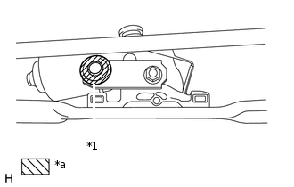
*1
Crank Arm Pivot
*a
MP grease
Apply MP grease to the crank arm pivot of the front wiper crank.
-
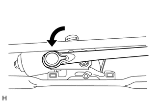
Connect the rod to the crank arm pivot of the front wiper crank.
INSTALL WINDSHIELD WIPER MOTOR AND LINK
-
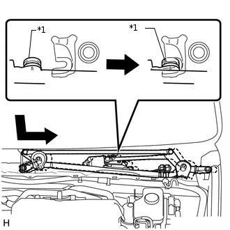
*1
Grommet
Attach the grommet as shown in the illustration.
7.0 N*m
71 kgf*cm
62 in.*lbf
Note:Be careful not to damage the windshield when installing the windshield wiper motor and link assembly.
Install the windshield wiper motor and link with the 2 bolts.
Connect the connector.
Attach the clamp.
-
INSTALL COWL TOP VENTILATOR LOUVER SUB-ASSEMBLY
-
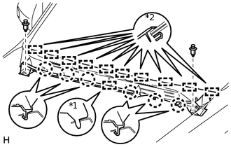
*1
Guide A
*2
Guide B
Attach the 10 guides (B).
Attach the 6 claws and guide (A) as shown in the illustration.
Install the 2 clips to the cowl top ventilator louver sub-assembly.
-
INSTALL CENTER NO. 2 COWL TOP VENTILATOR LOUVER
Attach the 2 claws and 3 guides to install the center No. 2 cowl top ventilator louver.
INSTALL HOOD TO COWL TOP SEAL
INSTALL FRONT WIPER ARM AND BLADE ASSEMBLY RH
Operate the wiper and stop the windshield wiper motor at the automatic stop position.
-
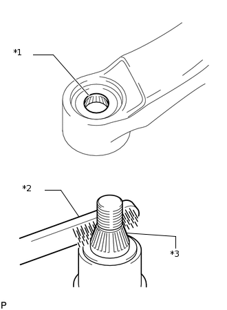
*1
Wiper Arm Serration
*2
Wire Brush
*3
Wiper Pivot Serration
When reusing the front wiper arm and blade assembly RH:
Clean the wiper arm serrations.
When reusing the windshield wiper link assembly:
Clean the wiper pivot serrations with a wire brush.
-
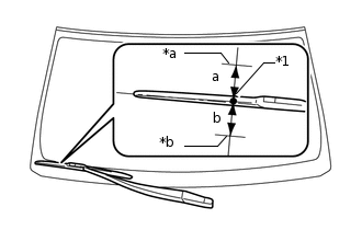
*1
Ceramic Dot
*a
Upper Limit
*b
Lower Limit
Install the front wiper arm and blade assembly RH with the nut to the position shown in the illustration.
25 N*m
255 kgf*cm
18 ft.*lbf
Standard
Area
Standard Condition
a
7.5 mm (0.295 in.)
b
7.5 mm (0.295 in.)
Tip:Hold the wiper arm by hand while tightening the nut.
Raise and lower the wiper arm a few times to confirm that it has settled to the specified position.
INSTALL FRONT WIPER ARM AND BLADE ASSEMBLY LH
-
*1
Wiper Arm Serration
*2
Wire Brush
*3
Wiper Pivot Serration
When reusing the front wiper arm and blade assembly LH:
Clean the wiper arm serrations.
When reusing the windshield wiper link assembly:
Clean the wiper pivot serrations with a wire brush.
-
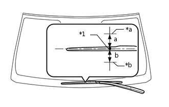
*1
Ceramic Dot
*a
Upper Limit
*b
Lower Limit
Install the front wiper arm and blade assembly LH with the nut to the position shown in the illustration.
25 N*m
255 kgf*cm
18 ft.*lbf
Standard
Area
Standard Condition
a
7.5 mm (0.295 in.)
b
7.5 mm (0.295 in.)
Tip:Hold the wiper arm by hand while tightening the nut.
Raise and lower the wiper arm a few times to confirm that it has settled to the specified position.
Operate the front wipers while spraying washer fluid on the windshield glass. Make sure that the front wipers function properly and there is no interference with the vehicle body.
-
INSTALL FRONT WIPER ARM HEAD CAP
-
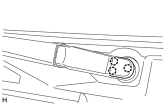
Attach the 3 claws to install the wiper arm head cap.
Tip:Use the same procedure described for the LH side.
-
INSTALL FRONT FENDER TO COWL SIDE SEAL LH
Attach the 5 claws to install the front fender to cowl side seal LH.
INSTALL FRONT FENDER TO COWL SIDE SEAL RH
Tip:Use the same procedure described for the LH side.
INSTALL FRONT FENDER SIDE PANEL PROTECTOR LH
Attach the 3 clips and guide to install the fender side panel.
INSTALL FRONT FENDER SIDE PANEL PROTECTOR RH
Tip:Use the same procedure described for the LH side.
INSTALL UPPER RADIATOR SUPPORT SEAL
INSTALL ENGINE ROOM SIDE COVER LH
Install the engine room side cover with the 4 clips.
INSTALL ENGINE ROOM SIDE COVER
Install the engine room side cover with the 4 clips.
CONNECT CABLE TO NEGATIVE BATTERY TERMINAL
Note:When disconnecting the cable, some systems need to be initialized after the cable is reconnected (Click hereClick hereClick here).