HYBRID CONTROL SYSTEM, Diagnostic DTC:P0560-117
| DTC Code | DTC Name |
|---|---|
| P0560-117 | System Voltage |
DESCRIPTION
-
Regular battery power is supplied to the BATT terminal of the hybrid control ECU in order to store DTCs and freeze frame data. Even if the power switch is turned off, back-up power is supplied.
| DTC No. | INF Code | DTC Detection Condition | Trouble Area |
|---|---|---|---|
| P0560 | 117 | Malfunction in the hybrid vehicle control ECU assembly back-up power source circuit (1 trip detection logic) |
|
WIRING DIAGRAM
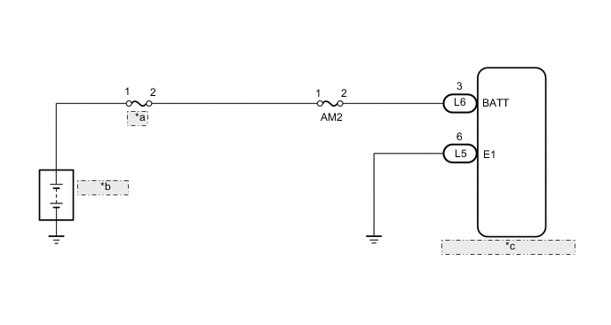
| *a | MAIN |
| *b | Auxiliary Battery |
| *c | Hybrid Vehicle Control ECU |
CAUTION / NOTICE / HINT
Tech Tips
After the repair, clear the DTCs and perform the following procedure to check that DTCs are not output.
-
Turn the power switch on (IG) and wait for 5 seconds or more.
PROCEDURE
-
CHECK CONNECTOR CONNECTION CONDITION (HYBRID VEHICLE CONTROL ECU CONNECTOR)
-
Check the connector connections and contact pressure of the relevant terminals for the hybrid vehicle control ECU connectors Click here.
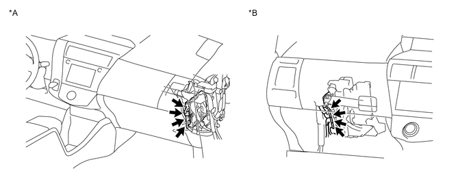
Text in Illustration *A for LHD *B for RHD OK The connectors are connected securely and there are no contact pressure problems.
NG 
CONNECT SECURELY
OK 
-
-
CHECK HARNESS AND CONNECTOR (HYBRID VEHICLE CONTROL ECU - AM2 FUSE)
-
Turn the power switch off.
-
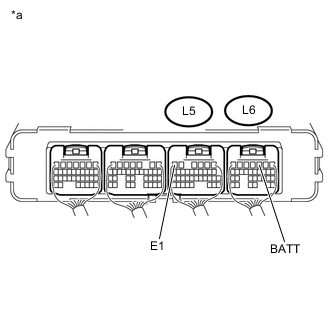
Text in Illustration *a Component without harness connected
(Hybrid Vehicle Control ECU)
Measure the voltage according to the value(s) in the table below.
Standard Voltage Tester Connection Condition Specified Condition L6-3 (BATT) - L5-6 (E1) Power switch off 11 to 14 V
OK
REPLACE HYBRID VEHICLE CONTROL ECU Click here
NG
-
-
CHECK FUSE (AM2)
-
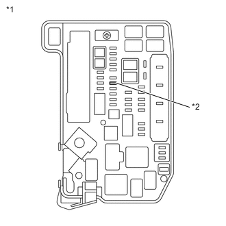
Text in Illustration *1 Engine Room Relay Block and Junction Block Assembly *2 AM2 Fuse Remove the AM2 fuse from the engine room relay block and junction block assembly.
-
Check if there is an open circuit in the AM2 fuse in the engine room relay block and junction block assembly.
OK There is no open circuit in the AM2 fuse. -
Install the AM2 fuse.
NG
REPLACE FUSE (AM2)
OK
-
-
CHECK HARNESS AND CONNECTOR (AM2 FUSE - BATTERY TERMINAL)
-
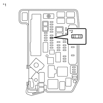
Text in Illustration *1 Engine Room Relay Block and Junction Block Assembly *2 AM2 Fuse Remove the AM2 fuse from the engine room relay block and junction block assembly.
-
Disconnect the cable from the negative (-) auxiliary battery terminal.
-
Disconnect the cable from the positive (+) auxiliary battery terminal
-
Measure the resistance according to the value(s) in the table below.
Standard Resistance Tester Connection Switch Condition Specified Condition 1 - Auxiliary battery positive (+) cable Power switch off Below 1 Ω 1 - Body ground Power switch off 10 kΩ or higher -
Connect the cable to the positive (+) auxiliary battery terminal.
-
Connect the cable to the negative (-) auxiliary battery terminal.
-
Install the AM2 fuse.
NG
REPAIR OR REPLACE HARNESS OR CONNECTOR
OK
-
-
CHECK HARNESS AND CONNECTOR (AM2 FUSE - HYBRID VEHICLE CONTROL ECU)
-
Remove the AM2 fuse from the engine room relay block and junction block assembly.
-
Disconnect the L6 hybrid vehicle control ECU connector.
-
Measure the resistance according to the value(s) in the table below.
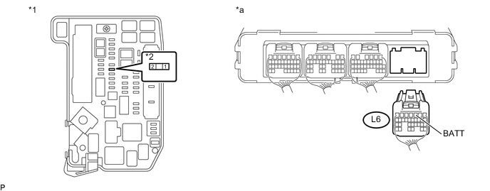
Text in Illustration *1 Engine Room Relay Block and Junction Block Assembly *2 AM2 Fuse *a Rear view of wire harness connector
(to Hybrid Vehicle Control ECU)
- - Standard Resistance Tester Connection Switch Condition Specified Condition 2 (AM2 fuse terminal) - L6-3 (BATT) Power switch off Below 1 Ω -
Reconnect the L6 hybrid vehicle control ECU connector.
-
Install the AM2 fuse.
OK
REPLACE HYBRID VEHICLE CONTROL ECU Click here
NG
REPAIR OR REPLACE HARNESS OR CONNECTOR
-