СИСТЕМА АВТОМАТИЧЕСКОЙ ТРАНСМИССИИ TCM Power Source Circuit
DESCRIPTION
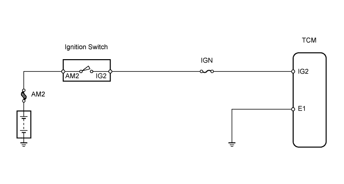
When the ignition switch is turned ON, battery voltage is applied to terminal IG2 of the TCM.
WIRING DIAGRAM
INSPECTION PROCEDURE
PROCEDURE
-
CHECK TCM (IG2 VOLTAGE)
-
Turn the ignition switch ON.
-
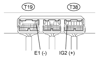
Measure the voltage of the TCM connectors.
Standard voltage Tester Connection Specified Condition T38-6 (IG2) - T19-1 (E1) 9 to 14 V
OK 
PROCEED TO NEXT CIRCUIT INSPECTION SHOWN IN PROBLEM SYMPTOMS TABLE
NG 
-
-
CHECK WIRE HARNESS (TCM - BODY GROUND)
-

Disconnect the T19 TCM connector.
-
Measure the resistance of the wire harness side connector.
Standard resistance Tester Connection Specified Condition T19-1 (E1)- Body ground Below 1 Ω
NG
REPAIR OR REPLACE HARNESS AND CONNECTOR
OK
-
-
INSPECT FUSE (IGN)
-

Remove the IGN fuse from the instrument panel junction block.
-
Measure the resistance of the fuse.
Standard resistance Below 1 Ω
NG
REPLACE FUSE
OK
-
-
INSPECT IGNITION SWITCH
-

Disconnect the I6 ignition switch connector.
-
Measure the resistance of the ignition switch.
Standard resistance Tester Connection Switch Condition Specified Condition 5 (AM2) - 6 (IG2) LOCK 10 kΩ or higher 5 (AM2) - 6 (IG2) ON Below 1 Ω
NG
REPLACE IGNITION SWITCH
OK 
REPAIR OR REPLACE HARNESS AND CONNECTOR (BATTERY - IGNITION SWITCH, IGNITION SWITCH - TCM)
-