BODY STRUCTURE
-
CONSTRUCTION
-
Floor Silencer
-
A floor silencer (asphalt sheet) is provided to reduce road and engine noise which enters the cabin.
Figure 1. Double Cab
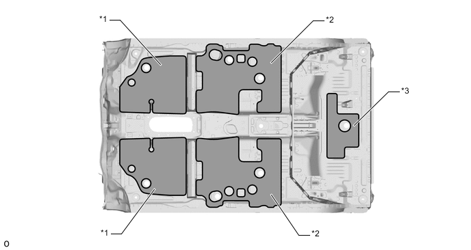
*1 Asphalt Sheet (Front Floor Silencer Sheet) *2 Asphalt Sheet (Front Floor Silencer Sheet CTR) *3 Asphalt Sheet (Rear Floor Silencer Sheet No. 2) - - Figure 2. Smart Cab
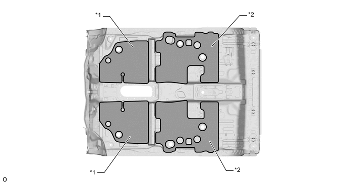
*1 Asphalt Sheet (Front Floor Silencer Sheet) *2 Asphalt Sheet (Front Floor Silencer Sheet CTR) Figure 3. Single Cab
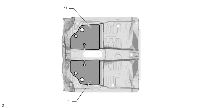
*1 Asphalt Sheet (Front Floor Silencer Sheet) - -
-
-
Sealing Material
-
Foamed materials, damping materials and sponge sealant are optimally placed in the side member opening and front header to suppress wind noise and road noise which enter the cabin.
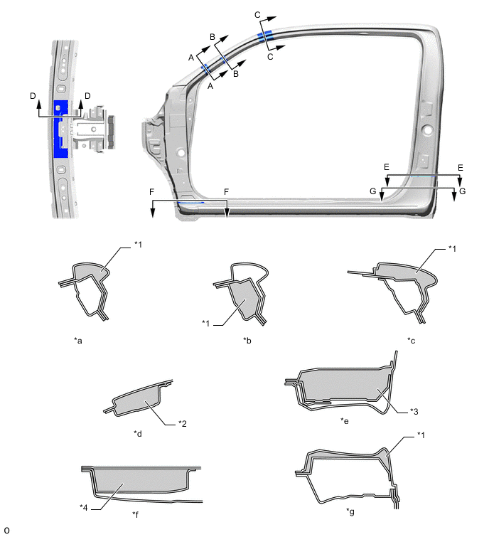
Figure 4. Double Cab
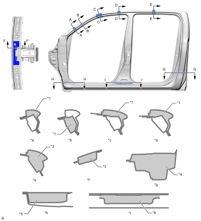
*1 Pillar Pad No. 2 *2 Pillar Pad No. 3 *3 Pillar Pad No. 1 *4 Quarter Panel Seal *5 Extension Front Body Pillar Pad Outer *6 Pillar Pad No. 5 *a A - A Cross Section *b B - B Cross Section *c C - C Cross Section *d D - D Cross Section *e E - E Cross Section *f F - F Cross Section *g G - G Cross Section *h H - H Cross Section *i I - I Cross Section - - Figure 5. Smart Cab
*1 Pillar Pad No. 2 *2 Pillar Pad No. 1 *3 Pillar Pad No. 5 *4 Extension Front Body Pillar Pad Outer *a A - A Cross Section *b B - B Cross Section *c C - C Cross Section *d D - D Cross Section *e E - E Cross Section *f F - F Cross Section *g G - G Cross Section - - Figure 6. Single Cab
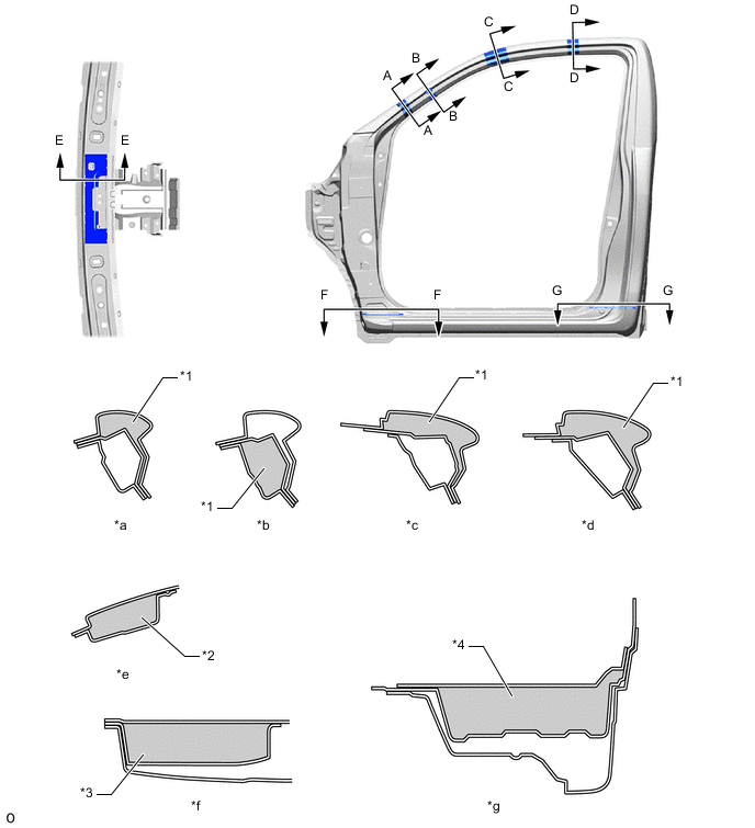
*1 Pillar Pad No. 2 *2 Pillar Pad No. 1 *3 Extension Front Body Pillar Pad Outer *4 Pillar Pad No. 5 *a A - A Cross Section *b B - B Cross Section *c C - C Cross Section *d D - D Cross Section *e E - E Cross Section *f F - F Cross Section *g G - G Cross Section - -
-
-
Sound Absorption and Insulation Structure around Engine Compartment
-
A hood insulator is provided on the rear of the hood sub-assembly. This achieves excellent sound insulation performance.
Figure 7. Hood Insulator (The illustration shows an example)
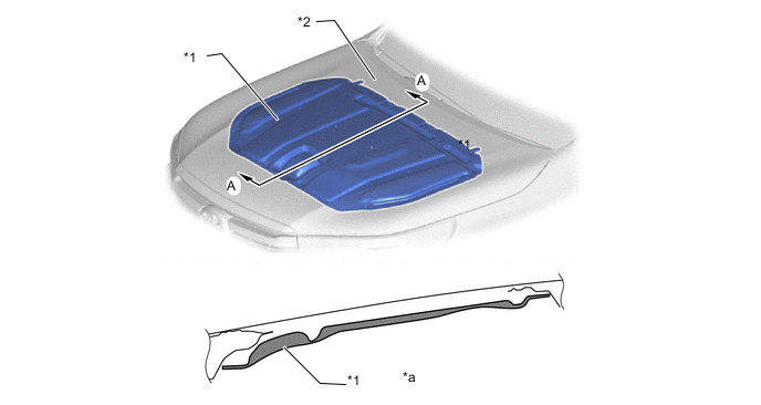
*1 Hood Insulator *2 Hood Sub-assembly *a A - A Cross Section - - -
The dash panel insulator outer (*1 in top illustration) is provided in the engine compartment side of the dash panel sub-assembly (*2 in illustration) and a dash panel insulator assembly (*1 in bottom illustration) is provided in the cabin side. This structure absorbs and insulates mechanical noise such as engine noise and ensures excellent quietness.
Figure 8. Dash Panel Insulator Outer (The illustration shows an example)
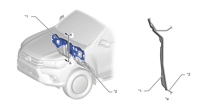
*1 Dash Panel Insulator Outer *2 Dash Panel Sub-assembly *a A - A Cross Section - - Figure 9. Dash Panel Insulator Assembly
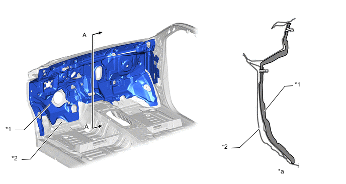
*1 Dash Panel Insulator Assembly *2 Dash Panel Sub-assembly *a A - A Cross Section - - -
A front side air guide (*1 in illustration) is provided between the front fender sub-assembly (*2 in illustration) and front fender apron sub-assembly (*3 in illustration) to reduce air intake noise which passes through the fender and enters the cabin.
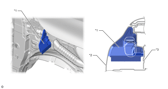
*1 Front Side Air Guide *2 Front Fender Sub-assembly *3 Front Fender Apron Sub-assembly - - -
A fender apron mudguard seal sub-assembly (*1 in illustration) is provided between the cowl top ventilator louver (*2 in illustration) and front fender apron sub-assembly (*3 in illustration) to reduce the engine noise that leaks from the engine compartment.
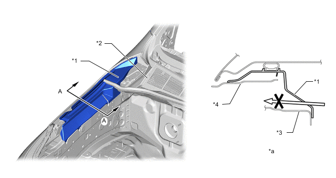
*1 Fender Apron Mudguard Seal Sub-assembly *2 Cowl Top Ventilator Louver *3 Front Fender Apron Sub-assembly *4 Front Fender Splash Shield Sub-assembly *a A - A Cross Section - - 
Noise Route - - -
The front fender side panel protector (*1 in illustration) is provided to reduce the engine noise which enters the cabin.
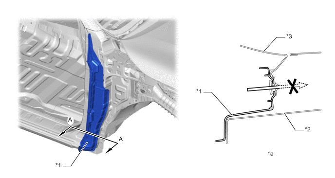
*1 Front Fender Side Panel Protector *2 Side Panel Outer *3 Front Fender Sub-assembly - - *a A - A Cross Section - - Noise Route - - -
The cowl top silencer pad No. 2 (*1 in illustration) covers the spot welds of the cowl top panel outer (*5 in illustration) and cowl top panel inner (*3 in illustration) to reduce the engine noise which enters the cabin.
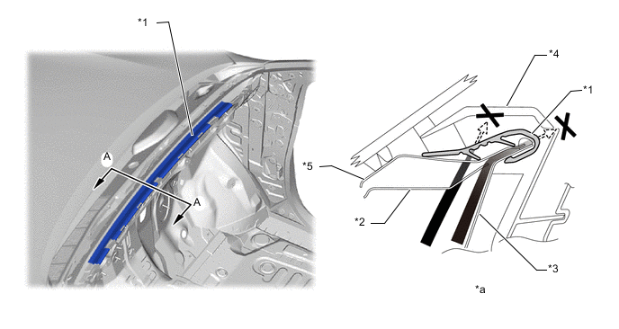
*1 Cowl Top Silencer Pad No. 2 *2 Cowl Top Reinforcement Inner No. 2 *3 Cowl Top Panel Inner *4 Instrument Panel Sub-assembly Upper *5 Cowl Top Panel Outer - - *a A - A Cross Section - - 
Noise Route - -
-
-