PRE-CRASH SAFETY SYSTEM TERMINALS OF ECU
-
CHECK DRIVING SUPPORT ECU ASSEMBLY

-
Measure the voltage and resistance according to the value(s) in the table below.
Tech Tips
If the result is not as specified, there may be a malfunction on the wire harness side.
Terminal No. (Symbol) Wiring Color Terminal Description Condition Specified Condition A72-7 (B) - A72-28 (GND) GR - W-B *1
B - W-B *2
Power source Engine switch on (IG) 11 to 14 V*1
10.5 to 16 V*2
Engine switch off Below 1 V A72-3 (BZ) - A72-28 (GND) R - W-B Skid control buzzer assembly output Engine switch on (IG), buzzer not sounding 11 to 14 V Engine switch on (IG), buzzer sounding Below 1 V A72-28 (GND) - Body ground W-B - Body ground Ground Always Below 1 Ω *1: w/o Stop and Start System
*2: w/ Stop and Start System
-
Check for pulses according to the value(s) in the table below.
Terminal No. (Symbol) Wiring Color Terminal Description Condition Specified Condition A72-8 (CA1P) - A72-28 (GND) Y - W-B *1
B - W-B *2
CAN communication signal Engine switch on (IG) Pulse generation
(See waveform 1)
A72-9 (CA1N) - A72-28 (GND) W - W-B CAN communication signal Engine switch on (IG) Pulse generation
(See waveform 2)
A72-10 (CA2H) - A72-28 (GND) B - W-B CAN communication signal Engine switch on (IG) Pulse generation
(See waveform 1)
A72-11 (CA2L) - A72-28 (GND) G - W-B CAN communication signal Engine switch on (IG) Pulse generation
(See waveform 2)
*1: for 2GR-FKS
*2: for 8AR-FTS
-
WAVEFORM 1
-
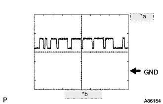
*a 1 V/DIV. *b 10 μsec./DIV. CAN communication signal
Item Content Terminal Name Between A72-8 (CA1P) - A72-28 (GND)
Between A72-10 (CA2H) - A72-28 (GND)
Tester Range 1 V/DIV., 10 μsec./DIV. Condition Engine switch on (IG) Tech Tips
The waveform varies depending on the CAN communication signal.
-
-
WAVEFORM 2
-
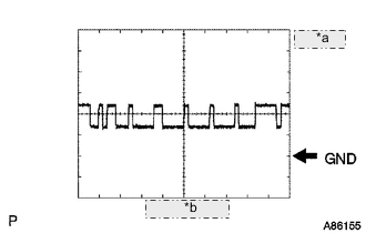
*a 1 V/DIV. *b 10 μsec./DIV. CAN communication signal
Item Content Terminal Name Between A72-9 (CA1N) - A72-28 (GND)
Between A72-11 (CA2L) - A72-28 (GND)
Tester Range 1 V/DIV., 10 μsec./DIV. Condition Engine switch on (IG) Tech Tips
The waveform varies depending on the CAN communication signal.
-
-
-
CHECK MILLIMETER WAVE RADAR SENSOR

-
Measure the voltage and resistance according to the value(s) in the table below.
Tech Tips
If the result is not as specified, there may be a malfunction on the wire harness side.
Terminal No. (Symbol) Wiring Color Terminal Description Condition Specified Condition A70-8 (IGB) - A70-1 (SGND) G - W-B *1
B - W-B *2
Power source Engine switch on (IG) 11 to 14 V*1
10.5 to 16 V*2
A70-1 (SGND) - Body ground W-B - Body ground Ground Always Below 1 Ω *1: w/o Stop and Start System
*2: w/ Stop and Start System
-
Check for pulses according to the value(s) in the table below.
Terminal No. (Symbol) Wiring Color Terminal Description Condition Specified Condition A70-3 (CA2H) - A70-1 (SGND) BR - W-B CAN communication signal Engine switch on (IG) Pulse generation
(See waveform 1)
A70-2 (CA2L) - A70-1 (SGND) V - W-B CAN communication signal Engine switch on (IG) Pulse generation
(See waveform 2)
A70-5 (CA1P) - A70-1 (SGND) L - W-B CAN communication signal Engine switch on (IG) Pulse generation
(See waveform 1)
A70-6 (CA1N) - A70-1 (SGND) GR - W-B CAN communication signal Engine switch on (IG) Pulse generation
(See waveform 2)
-
WAVEFORM 1
-
*a 1 V/DIV. *b 10 μsec./DIV. CAN communication signal
Item Content Terminal Name Between A70-3 (CA2H) and A70-1 (SGND)
Between A70-5 (CA1P) and A70-1 (SGND)
Tester Range 1 V/DIV., 10 μsec./DIV. Condition Engine switch on (IG) Tech Tips
The waveform varies depending on the CAN communication signal.
-
-
WAVEFORM 2
-
*a 1 V/DIV. *b 10 μsec./DIV. CAN communication signal
Item Content Terminal Name Between A70-2 (CA2L) and A70-1 (SGND)
Between A70-6 (CA1N) and A70-1 (SGND)
Tester Range 1 V/DIV., 10 μsec./DIV. Condition Engine switch on (IG) Tech Tips
The waveform varies depending on the CAN communication signal.
-
-