AIR CONDITIONING UNIT INSTALLATION
CAUTION / NOTICE / HINT
Use the same procedure for RHD and LHD vehicles.
The procedure listed below is for LHD vehicles.
PROCEDURE
INSTALL BLOWER ASSEMBLY
INSTALL NO. 3 AIR DUCT SUB-ASSEMBLY
-
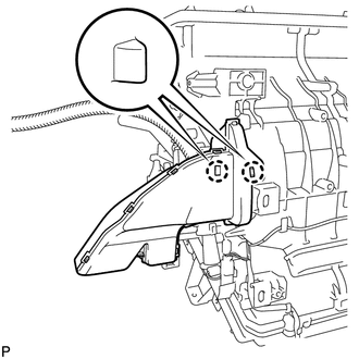
Attach the 2 claws to install the No. 3 air duct sub-assembly.
-
INSTALL NO. 2 AIR DUCT SUB-ASSEMBLY
-
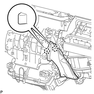
Attach the 2 claws to install the No. 2 air duct sub-assembly.
-
TEMPORARILY INSTALL AIR CONDITIONING UNIT
-

Temporarily install the air conditioning unit with the bolt and nut.
Note:Be sure to support the air conditioning unit when installing it because failure to do so may cause the bracket of the air conditioning unit to break.
When installing the air conditioning unit, eliminate static electricity by touching the vehicle body to prevent the components from being damaged.
-
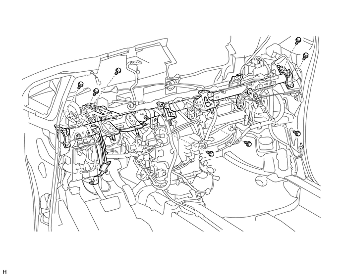
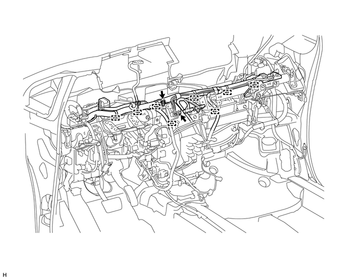
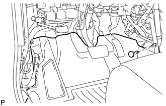
INSTALL INSTRUMENT PANEL REINFORCEMENT ASSEMBLY
Install the instrument panel reinforcement assembly with the 8 bolts.
Connect each connector.
Attach each clamp.
Connect the wire harness and junction block and install each bolt.
for bolt A
24 N*m
245 kgf*cm
18 ft.*lbf
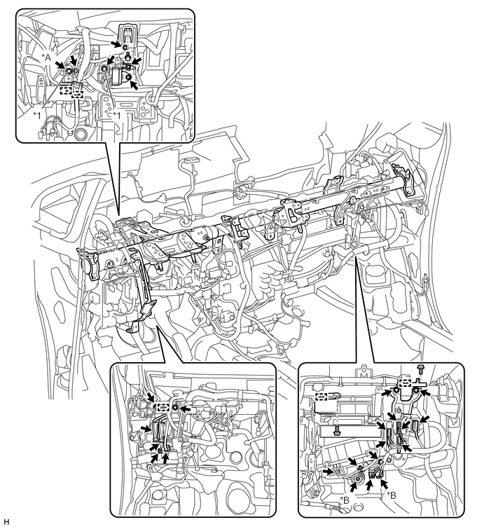
Table 1. Text in Illustration *A
except Manual Transaxle
*B
w/ PTC Heater
*1
Specified Torque Bolt A
-
-
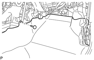
Attach each clamp and connect the wire harness.
Install the ground wire with the 2 bolts.
INSTALL AIR CONDITIONING UNIT
Tighten the bolt of the air conditioning unit.
9.8 N*m
100 kgf*cm
87 in.*lbf
Tighten the nut of the air conditioning unit.
9.8 N*m
100 kgf*cm
87 in.*lbf
Connect the drain cooler hose.
INSTALL REAR NO. 2 AIR DUCT
-
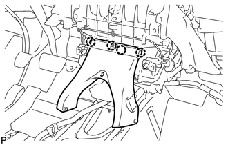
Attach the 4 claws to install the rear No. 2 air duct.
-
INSTALL INSTRUMENT PANEL BRACE ASSEMBLY
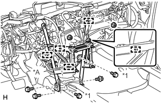
Install the instrument panel brace assembly with the 3 bolts, 2 screws and 2 nuts.
Screw
9.8 N*m
100 kgf*cm
87 in.*lbf
Table 2. Text in Illustration *A
except Manual Transaxle
*1
Screw
Attach each clamp.
Connect the connector.
INSTALL CENTER INSTRUMENT PANEL TO COWL BRACE
-
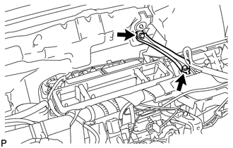
Install the center instrument panel to cowl brace with the 2 bolts.
-
INSTALL LOWER DEFROSTER NOZZLE ASSEMBLY
-
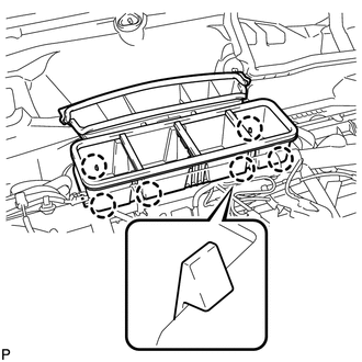
Attach the 6 claws to install the lower defroster nozzle assembly.
-
INSTALL NO. 1 AIR DUCT SUB-ASSEMBLY
-
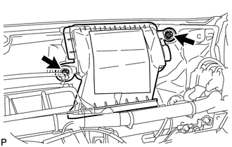
Install the No. 1 air duct sub-assembly with the 2 nuts.
9.8 N*m
100 kgf*cm
87 in.*lbf
-
INSTALL REAR NO. 1 AIR DUCT
-
Attach the 2 claws to install the rear No. 1 air duct.
-
Install the floor carpet with the clip.
-
INSTALL REAR NO. 3 AIR DUCT
-
Attach the 2 claws to install the rear No. 3 air duct.
-
Install the floor carpet with the clip.
-
INSTALL LOWER INSTRUMENT PANEL SUB-ASSEMBLY
INSTALL COWL SIDE TRIM BOARD LH
INSTALL FRONT DOOR SCUFF PLATE LH
INSTALL COWL SIDE TRIM BOARD RH
INSTALL FRONT DOOR SCUFF PLATE RH
INSTALL STEERING COLUMN ASSEMBLY
INSTALL INSTRUMENT PANEL SAFETY PAD SUB-ASSEMBLY
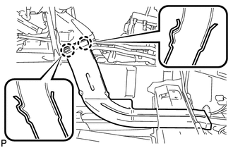
CONNECT HEATER OUTLET WATER HOSE AND HEATER INLET WATER HOSE
-
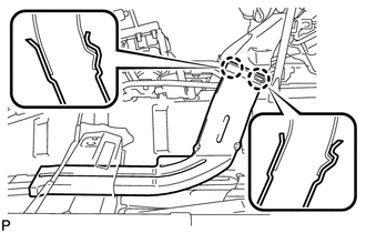
Connect the heater outlet water hose and heater inlet water hose with the paint mark facing up and attach the clip shown in the illustration.
Table 3. Text in Illustration *1
Paint Mark (Width: 5 mm)
*2
Paint Mark (Width: 2 mm)
-
CONNECT AIR CONDITIONER TUBE AND ACCESSORY ASSEMBLY (for HFO-1234yf(R1234yf))
Remove the attached vinyl tape from the pipe and air conditioning unit.
Sufficiently apply compressor oil to 2 new O-rings and the fitting surface of the air conditioning tube and accessory.
Compressor oil
ND-OIL 12 or equivalent
Install the 2 O-rings to the air conditioning tube and accessory.
-
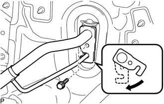
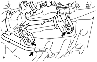
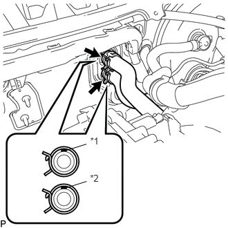
Securely connect the air conditioning tube and accessory to the air conditioning unit.
Move the hook connector in the direction indicated by the arrow in the illustration and install the bolt.
9.8 N*m
100 kgf*cm
87 in.*lbf
CONNECT AIR CONDITIONING TUBE AND ACCESSORY ASSEMBLY (for HFC-134a(R134a))
Remove the attached vinyl tape from the tube and air conditioning unit.
Sufficiently apply compressor oil to a new O-ring and the fitting surface of the air conditioning tube assembly.
Compressor oil
ND-OIL 8 or equivalent
Install the O-ring to the air conditioning tube and accessory.
Connect the air conditioner tube and accessory assembly.
CONNECT SUCTION PIPE SUB-ASSEMBLY (for HFC-134a(R134a))
Remove the attached vinyl tape from the pipe and air conditioning unit.
Sufficiently apply compressor oil to a new O-ring and the fitting surface of the suction pipe sub-assembly.
Compressor oil
ND-OIL 8 or equivalent
Install the O-ring to the suction pipe sub-assembly.
-
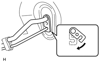
Securely connect the suction pipe to the air conditioning unit.
Move the hook connector in the direction indicated by the arrow in the illustration and install the bolt.
9.8 N*m
100 kgf*cm
87 in.*lbf
INSTALL OUTER COWL TOP PANEL
INSTALL DIFFERENTIAL PRESSURE SENSOR ASSEMBLY (for DPF)
INSTALL WINDSHIELD WIPER MOTOR AND LINK ASSEMBLY
INSTALL COWL TOP VENTILATOR LOUVER LH
INSTALL COWL TOP VENTILATOR LOUVER RH
INSTALL HOOD TO COWL TOP SEAL
INSTALL FRONT WIPER ARM AND BLADE ASSEMBLY LH
INSTALL FRONT WIPER ARM AND BLADE ASSEMBLY RH
INSTALL FRONT WIPER ARM HEAD CAP
INSTALL NO. 2 CYLINDER HEAD COVER (for ZR Series Engine)
INSTALL NO. 1 ENGINE COVER (for 1WW)
CHARGE REFRIGERANT
for HFC-134a(R134a):
for HFO-1234yf(R1234yf):
ADD ENGINE COOLANT (for 1ZR-FAE)
ADD ENGINE COOLANT (for 2ZR-FAE)
ADD ENGINE COOLANT (for 1WW)
CONNECT CABLE TO NEGATIVE BATTERY TERMINAL
CAUTION:When disconnecting the cable, some systems need to be initialized after the cable is reconnected (Click here).
INSPECT FOR COOLANT LEAK (for 1ZR-FAE)
INSPECT FOR COOLANT LEAK (for 2ZR-FAE)
INSPECT FOR COOLANT LEAK (for 1WW)
CHECK SRS WARNING LIGHT
WARM UP ENGINE
for HFC-134a(R134a):
for HFO-1234yf(R1234yf):
CHECK FOR REFRIGERANT GAS LEAK
for HFC-134a(R134a):
for HFO-1234yf(R1234yf):