FRONT EVAPORATOR TEMPERATURE SENSOR INSTALLATION
CAUTION / NOTICE / HINT
Tech Tips
-
Use the same procedure for RHD and LHD vehicles.
-
The procedure listed below is for LHD vehicles.
PROCEDURE
-
INSTALL NO. 1 COOLER THERMISTOR
-
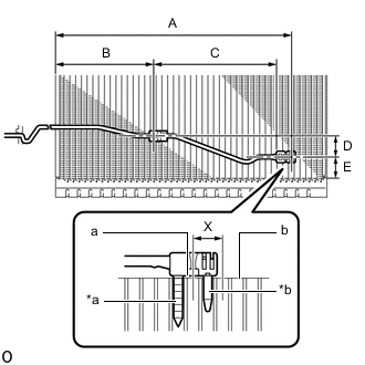
*a Fixed Part *b Sensor Part Install the No. 1 cooler thermistor as shown in the illustration.
Installation Position Part Length A 275.5 mm (10.8 in.)(41 Fins) B 114.7 mm (4.52 in.)(17 Fins) C 143.6 mm (5.65 in.) D 25 mm (0.984 in.) E 20 to 30 mm (0.787 to 1.18 in.) Note
-
Be sure to insert the No. 1 cooler thermistor only once because reinserting it into the same position will not allow it to be firmly secured.
-
When reusing the No. 1 cooler evaporator sub-assembly, insert the sensor part of the No. 1 cooler thermistor one row from the row that had been used previously (X in the illustration).
-
After inserting the No. 1 cooler thermistor, do not apply excessive force to the wire.
-
Directly insert the No. 1 cooler thermistor until the edge of the plastic case "a" comes into contact with the No. 1 cooler evaporator sub-assembly "b".
-
-
-
INSTALL NO. 1 COOLER EVAPORATOR SUB-ASSEMBLY
-
INSTALL NO. 4 AIR CONDITIONING RADIATOR DAMPER SERVO SUB-ASSEMBLY
-
INSTALL NO. 2 AIR CONDITIONING RADIATOR DAMPER SERVO SUB-ASSEMBLY
-
INSTALL NO. 3 COOLING UNIT BRACKET (for LHD)
-
INSTALL NO. 1 COOLER COVER
-
INSTALL COOLER EXPANSION VALVE
-
INSTALL AIR CONDITIONING TUBE ASSEMBLY
-
INSTALL NO. 2 COOLER COVER
-
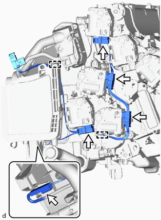
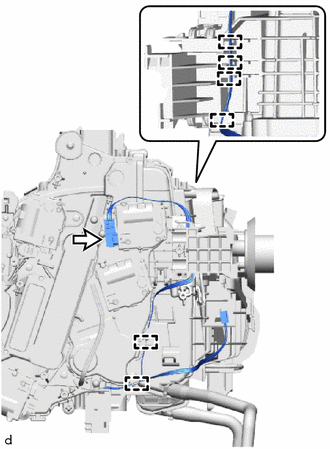
INSTALL AIR CONDITIONING HARNESS ASSEMBLY (for LHD)
-
for 4 Zone Type:
-
Connect the 2 connectors.
-
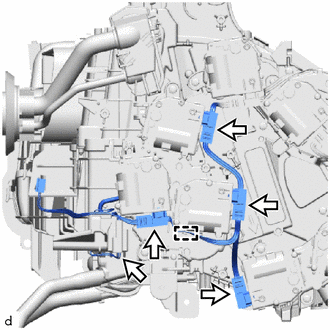
Connect the 5 connectors.
-
Attach the guide.
-
-
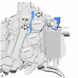
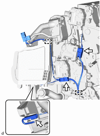
for Dual Type:
-
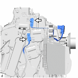
Connect the 2 connectors.
-
Connect the 3 connectors.
-
-
-
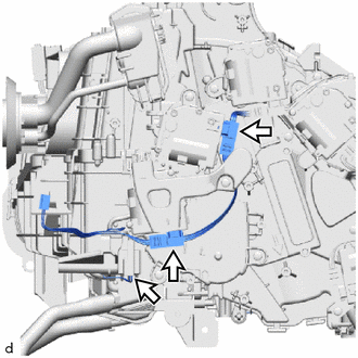
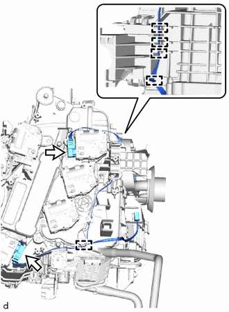
INSTALL AIR CONDITIONING HARNESS ASSEMBLY (for RHD)
-
for 4 Zone Type:
-
Connect the 2 connectors.
-
Attach the guide.
-
Connect the 5 connectors.
-
Attach the guide.
-
-
for Dual Type:
-
Connect the connector.
-
Attach the guide.
-
Connect the 3 connectors.
-
Attach the guide.
-
-
-
INSTALL HEATER RADIATOR UNIT SUB-ASSEMBLY
-
INSTALL NO. 3 COOLING UNIT BRACKET (for RHD)
-
INSTALL COOLING UNIT PARTS
-
INSTALL HEATER GROMMET
-
INSTALL BLOWER ASSEMBLY