VALVE CLEARANCE ADJUSTMENT
PROCEDURE
REMOVE INTAKE MANIFOLD
REMOVE CYLINDER HEAD COVER SUB-ASSEMBLY
REMOVE CYLINDER HEAD COVER GASKET
SET NO. 1 CYLINDER TO TDC/EXHAUST
INSPECT VALVE CLEARANCE
-
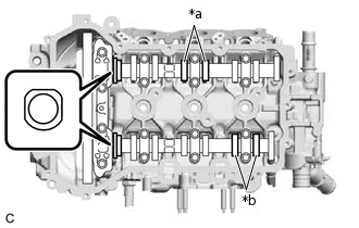
*a
Intake Side
*b
Exhaust Side
Check only the valves shown in the illustration.
Using a feeler gauge, measure the clearance between the valve lifter and camshaft.
Valve Clearance (Cold)
Intake Side
0.160 to 0.260 mm (0.00630 to 0.01024 in.)
Exhaust Side
0.350 to 0.430 mm (0.01378 to 0.01693 in.)
Tip:Insert the feeler gauge from the spark plug side (center).
Record any out-of-specification valve clearance measurements. They will be used later to determine the required replacement valve lifters.
-
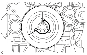
Turn the crankshaft 1 revolution (240°).
-
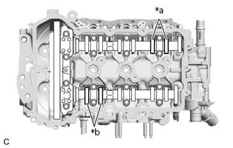
*a
Intake Side
*b
Exhaust Side
Check only the valves shown in the illustration.
Using a feeler gauge, measure the clearance between the valve lifter and camshaft.
Valve Clearance (Cold)
Intake Side
0.160 to 0.260 mm (0.00630 to 0.01024 in.)
Exhaust Side
0.350 to 0.430 mm (0.01378 to 0.01693 in.)
Tip:Insert the feeler gauge from the spark plug side (center).
Record any out-of-specification valve clearance measurements. They will be used later to determine the required replacement valve lifters.
Turn the crankshaft 1 revolution (240°).
-
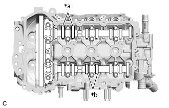
*a
Intake Side
*b
Exhaust Side
Check only the valves shown in the illustration.
Using a feeler gauge, measure the clearance between the valve lifter and camshaft.
Valve Clearance (Cold)
Intake Side
0.160 to 0.260 mm (0.00630 to 0.01024 in.)
Exhaust Side
0.350 to 0.430 mm (0.01378 to 0.01693 in.)
Tip:Insert the feeler gauge from the spark plug side (center).
Record any out-of-specification valve clearance measurements. They will be used later to determine the required replacement valve lifters.
-
ADJUST VALVE CLEARANCE
Remove the camshaft and No. 2 camshaft.
Remove the valve lifters.
-
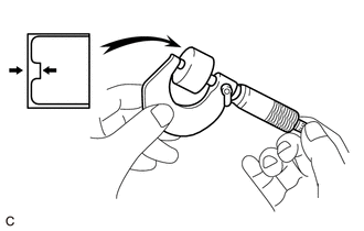
Using a micrometer, measure the thickness of the removed valve lifters.
Calculate the thickness of a new lifter so that the valve clearance comes within the specified value.
A
Thickness of new lifter
B
Thickness of used lifter
C
Measured valve clearance
Valve Clearance
Intake A = B + (C - 0.21 mm (0.0083 in.))
Exhaust A = B + (C - 0.38 mm (0.0150 in.))
Tip:Select a new lifter with a thickness as close to the calculated values as possible.
Lifters are available in 22 sizes in increments of 0.040 mm (0.0016 in.), from 2.72 mm (0.1071 in.) to 3.56 mm (0.1402 in.).
Refer to the following Valve Lifter Selection Charts.
Install the valve lifters.
Install the camshaft and No. 2 camshaft.
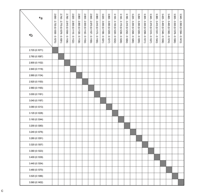
*a
Thickness of New Lifter mm (in.)
*b
New Lifter Thickness mm (in.)
INSTALL CYLINDER HEAD COVER GASKET
INSTALL CYLINDER HEAD COVER SUB-ASSEMBLY
INSTALL INTAKE MANIFOLD
CHECK ENGINE OIL LEVEL
INSPECT FOR OIL LEAK