ROOF HEADLINING REASSEMBLY

PROCEDURE
-
INSTALL NO. 1 ROOF WIRE
-
Apply new double-sided tape to locations shown in the illustration while aligning the tape with the markings on the roof headlining.
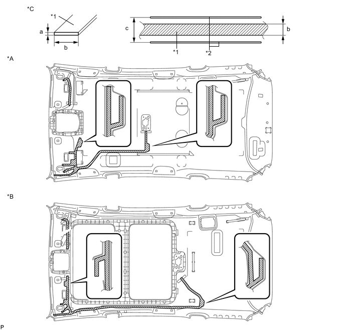
Text in Illustration *A except Glass Roof *B for Glass Roof *C Tape Attachment Locations (Reference) - - *1 Double-sided Tape *2 Marking Double-sided Tape Size Item Dimension a 1 mm (0.0394 in.) b 10 mm (0.394 in.) c 20 mm (0.787 in.) Note
Securely apply the double-sided tape to prevent it from being out of alignment and peeling off.
-
Peel off the release paper from the double-sided tape.
-
Attach the No. 1 roof wire along the double-sided tape so that the marking surface of the wire harness faces downward.
-
Install the No. 1 roof wire to the roof headlining.
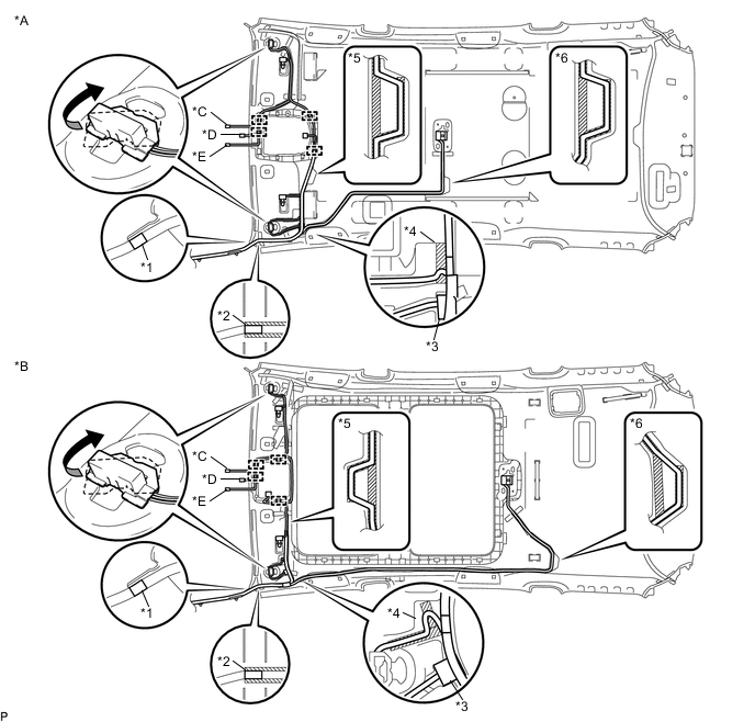
Text in Illustration *A except Glass Roof *B for Glass Roof *C for LHD with Rain Sensor *D w/ EC Mirror *E for RHD with Rain Sensor - - *1 Pink Marking Tape (A) *2 Marking Tape (B) *3 Joint Box *4 Adjustment Area (1) *5 Adjustment Area (2) *6 Adjustment Area (3)
-
Align the pink marking tape (A) on the front part of the No. 1 roof wire with the front tab of the roof headlining.
Tech Tips
Align the pink marking tape (A) with the front tab of the roof headlining so that the part number label is facing the inside of the cabin.
-
Align the marking tape (B) on the No. 1 roof wire with the markings on the roof headlining.
-
Align the joint box with the roof headlining marking, and secure it using the tape.
-
Attach the No. 1 roof wire, starting from the joint box to the pink marking tape (A) part while aligning it with the double-sided tape.
Note
-
Securely attach the No. 1 roof wire.
-
If any of the No. 1 roof wire is left loose, this will cause abnormal noise. Make sure to attach the No. 1 roof wire without leaving any loose.
-
-
Turn the visor connector LH clockwise approximately 45° to install the connector to the roof headlining assembly.
-
Attach the No. 1 roof wire, starting from the visor connector LH to the joint box part while aligning it with the double-sided tape.
Note
-
Securely attach the No. 1 roof wire.
-
If any of the No. 1 roof wire is left loose, this will cause abnormal noise. Make sure to attach the No. 1 roof wire without leaving any loose.
Tech Tips
Secure the extra length of the No. 1 roof wire in the adjustment area (1).
-
-
Engage each clamp.
-
Turn the visor connector RH clockwise approximately 45° to install the connector to the roof headlining assembly.
-
Attach the No. 1 roof wire, starting from the visor connector RH to the clamp while aligning it with the double-sided tape.
Note
-
Securely attach the No. 1 roof wire.
-
If any of the No. 1 roof wire is left loose, this will cause abnormal noise. Make sure to attach the No. 1 roof wire without leaving any loose.
-
-
Attach the No. 1 roof wire, starting from the clamp to the adjustment area (2) while aligning it with the double-sided tape.
Note
-
Securely attach the No. 1 roof wire.
-
If any of the No. 1 roof wire is left loose, this will cause abnormal noise. Make sure to attach the No. 1 roof wire without leaving any loose.
-
-
Attach the No. 1 roof wire, starting from the joint box to the adjustment area (2) while aligning it with the double-sided tape.
Note
-
Securely attach the No. 1 roof wire.
-
If any of the No. 1 roof wire is left loose, this will cause abnormal noise. Make sure to attach the No. 1 roof wire without leaving any loose.
Tech Tips
Secure the extra length of the No. 1 roof wire in the adjustment area (2).
-
-
Attach the No. 1 roof wire, starting from the joint box to the adjustment area (3) while aligning it with the double-sided tape.
Note
-
Securely attach the No. 1 roof wire.
-
If any of the No. 1 roof wire is left loose, this will cause abnormal noise. Make sure to attach the No. 1 roof wire without leaving any loose.
-
-
Attach the No. 1 roof wire, starting from the installation position of the No. 1 room light assembly to the adjustment area (3), while aligning it with the double-sided tape.
Note
-
Securely attach the No. 1 roof wire.
-
If any of the No. 1 roof wire is left loose, this will cause abnormal noise. Make sure to attach the No. 1 roof wire without leaving any loose.
Tech Tips
Secure the extra length of the No. 1 roof wire in the adjustment area (3).
-
-
-
Install adhesive tape to the No. 1 roof wire.
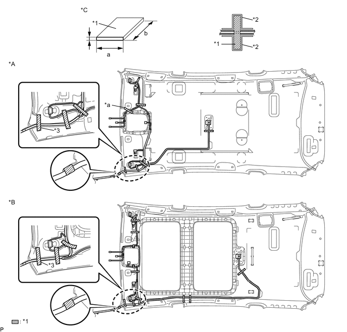
Text in Illustration *A except Glass Roof *B for Glass Roof *C Tape Attachment Locations (Reference) - - *1 Adhesive Tape *2 Marking *3 Marking (A) - - *a w/ Rain Sensor or w/ EC Mirror - - Adhesive Tape Size Item Dimension a 20 mm (0.787 in.) b 110 mm (4.33 in.) or more Tech Tips
-
Please avoid holding (touching) the adhesive side as much when taping.
-
Stick the adhesive tape at the position, which No. 1 roof wire would be able to line on the center of tape.
-
If taped on the edge, adhesive width is too small to hold the No. 1 roof wire.
-
After taping, please press all the area of taping with 50 kPa (0.5 kg/cm2,7.25 psi) or more using your finger.
-
Apply adhesive tape by aligning it with the front tab of the roof headlining.
-
Apply adhesive tape by aligning it with the marking (A) on the roof headlining.
-
Apply adhesive tape by aligning it with the markings on the roof headlining.
-
-
-
INSTALL REAR ROOF SILENCER PAD
-
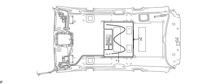
Align the markings on the roof headlining with the rear roof silencer pad and install the pad using hot-melt glue as shown in the illustration.
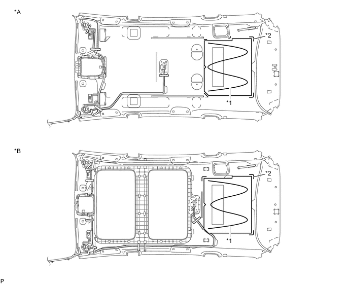
Text in Illustration *A except Glass Roof *B for Glass Roof *1 Hot-melt Glue *2 Marking
-
-
INSTALL CENTER ROOF SILENCER PAD (except Glass Roof)
-
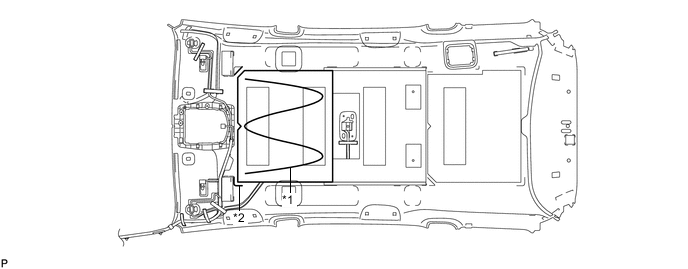
Align the markings on the roof headlining with the center roof silencer pad and install the pad using hot-melt glue as shown in the illustration.
Text in Illustration *1 Hot-melt Glue *2 Marking
-
-
INSTALL FRONT ROOF SILENCER PAD (except Glass Roof)
-
Align the markings on the roof headlining with the front roof silencer pad and install the pad using hot-melt glue as shown in the illustration.
Text in Illustration *1 Hot-melt Glue *2 Marking
-
-
INSTALL VANITY LIGHT ASSEMBLY
-
Install the vanity light assembly Click here.
Tech Tips
Use the same procedure for the other vanity light.
-
-
INSTALL NO. 2 ANTENNA CORD SUB-ASSEMBLY