СИСТЕМА SFI, Diagnostic DTC:P0335, P0339
| DTC Code | DTC Name |
|---|---|
| P0335 | Crankshaft Position Sensor "A" Circuit |
| P0339 | Crankshaft Position Sensor "A" Circuit Intermittent |
DESCRIPTION
The crankshaft position sensor (NE) signal consists of a magnet, iron core and pickup coil.
The NE signal plate (crankshaft position sensor plate) has 34 teeth and is installed on the crankshaft. The NE signal sensor generates 34 signals at every engine revolution. The ECM detects the crankshaft angle and the engine revolution based on the NE signal, and the cylinder and the angle of the Variable Valve Timing (VVT) based on the combination of the VV and NE signal.
| DTC No. | DTC Detection Condition | Trouble Area |
|---|---|---|
| P0335 | When one of the following conditions is met:
|
|
| P0339 | Conditions (a), (b) and (c) are met when no crankshaft position sensor signal is input for 0.05 sec. or more. (a) Engine revolution 1,000 rpm or more (b) STA signal is OFF (c) 3 sec. or more have lapsed after STA signal is switched from ON to OFF |
-
-
Reference:
-
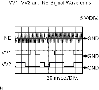
The waveform is as shown in the illustration.
Item Contact Symbols (Terminal No.) NE+ (E17-21) - NE- (E17-20)
VV1+ (E17-19) - VV1- (E17-29)
VV2+ (E17-18) - VV2- (E17-28)
Tool Setting 5 V/DIV., 20 msec./DIV. Condition Idling
WIRING DIAGRAM
INSPECTION PROCEDURE
Tech Tips
-
If no problem is found by this diagnostic troubleshooting procedure, troubleshoot the engine mechanical systems.
-
Check the engine speed. The engine speed can be checked by using the intelligent tester. To check, follow the operation below:
-
Connect the intelligent tester to the DLC3.
-
Start the engine.
-
Turn the tester ON.
-
Enter the following menus: Powertrain / Engine and ECT / Data List / Engine Speed.
The engine speed may be indicated as 0 despite the engine revolving normally. This is caused by a lack of NE signals from the crankshaft position sensor. Alternatively, the engine speed may be indicated as lower than the actual engine speed if the crankshaft position sensor output voltage is insufficient.
-
Read freeze frame data using the intelligent tester. Freeze frame data records the engine conditions when a malfunction is detected. When troubleshooting, freeze frame data can help determine if the vehicle was running or stopped, if the engine was warmed up or not, if the air-fuel ratio was lean or rich, and other data from the time the malfunction occurred.
PROCEDURE
-
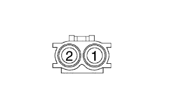
INSPECT CRANKSHAFT POSITION SENSOR (RESISTANCE)
-
Disconnect the crankshaft position sensor connector.
-
Measure the resistance of the sensor.
Standard resistance Tester Connection Specified Condition 1 - 2 1,630 to 2,740 Ω at cold 1 - 2 2,065 to 3,225 Ω at hot Tech Tips
The terms cold and hot refer to the temperature of the coils. Cold means approximately -10 to 50°C (14 to 122°F). Hot means approximately 50 to 100°C (122 to 212°F).
NG 
REPLACE CRANKSHAFT POSITION SENSOR
OK 
-
-
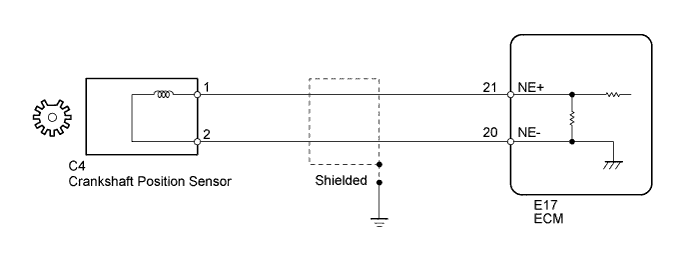
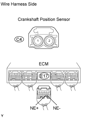
CHECK WIRE HARNESS (CRANKSHAFT POSITION SENSOR - ECM)
-
Disconnect the C4 crankshaft position sensor connector.
-
Disconnect the E17 ECM connector.
-
Measure the resistance of the wire harness side connectors.
Standard resistance Tester Connection Specified Condition C4-1 (NE+) - E17-21 (NE+) Below 1 Ω C4-2 (NE-) - E17-20 (NE-) Below 1 Ω C4-1 (NE+) - E17-21 (NE+) - Body ground 10 kΩ or higher C4-2 (NE-) - E17-20 (NE-) - Body ground 10 kΩ or higher
NG
REPAIR OR REPLACE HARNESS AND CONNECTOR
OK
-
-
CHECK SENSOR INSTALLATION (CRANKSHAFT POSITION SENSOR)
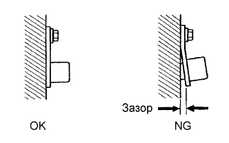
-
Check the crankshaft position sensor installation.
OK Sensor is installed correctly.
NG
TIGHTEN CRANKSHAFT POSITION SENSOR
OK
-
-
CHECK CRANKSHAFT POSITION SENSOR PLATE (TEETH OF SENSOR PLATE)
-
Check the teeth of the sensor plate.
OK Sensor plate does not have any cracks or deformation.
NG
REPLACE CRANKSHAFT POSITION SENSOR PLATE
OK 
REPLACE ECM
-