KINETIC DYNAMIC SUSPENSION SYSTEM, Diagnostic DTC:C1851/51 and C1853/53
| DTC Code | DTC Name |
|---|---|
| C1851/51 | Low Pressure Malfunction in Upside of KDSS System |
| C1853/53 | High Pressure Malfunction in Upside of KDSS System |
DESCRIPTION
In the KDSS hydraulic circuit, the fluid is contained under pressure. If the fluid temperature is 20°C (68°F), the pressure is approximately 3.0 MPa (30.6 kgf/cm2, 435 psi).
DTC No. |
Detection Item |
DTC Detection Condition |
Trouble Area |
|---|---|---|---|
C1851/51 |
Low Pressure Malfunction in Upside of KDSS System |
The sensor output is 0.9 MPa (9.2 kgf/cm2, 130 psi) or less for 5 min. continuously with the engine switch on (IG). |
|
C1853/53 |
High Pressure Malfunction in Upside of KDSS System |
The sensor output is 8.8 MPa (89.7 kgf/cm2, 1276 psi) or more for 20 sec. continuously with the engine switch on (IG). |
|
CAUTION / NOTICE / HINT
When these DTCs are output, perform the hydraulic circuit inspection first (Click here).
If the DTCs cannot be cleared even after the hydraulic circuit inspection, perform the electrical circuit inspection by following the procedures below.
PROCEDURE
INSPECT FOR FLUID LEAK
Inspect for fluid leaks.
OK
No fluid leaks.
Result
Result
OK
NG
NG REPAIR FLUID LEAK OR REPLACE PARTS AS NECESSARY
CHECK ANY OTHER DTCS OUTPUT (DTC C1812/12, C1831/31 AND/OR C1832/32)
Check if DTC C1812/12, C1831/31 and/or C1832/32 is output.
Chassis > KDSS > Trouble Codes
Result
Result
Proceed to
No output
A
DTC C1812/12, C1831/31 and/or C1832/32 is output
B
INSPECT STABILIZER CONTROL SOLENOID VALVE (CHECK IF VALVE STUCK)
Disconnect the stabilizer control with accumulator housing assembly connector.
-
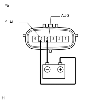
*a
Component without harness connected
(Stabilizer Control with Accumulator Housing Assembly)
Check for an operating sound of the stabilizer control solenoid valve.
for Upper Chamber:
Connect terminal 5 (SLAL) to the positive (+) battery terminal, and terminal 4 (AUG) to the negative (-) battery terminal.
OK
An operating sound (click sound) can be heard.
-
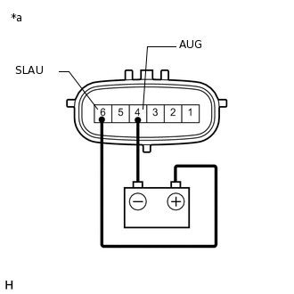
*a
Component without harness connected
(Stabilizer Control with Accumulator Housing Assembly)
for Lower Chamber:
Connect terminal 6 (SLAU) to the positive (+) battery terminal, and terminal 4 (AUG) to the negative (-) battery terminal.
OK
An operating sound (click sound) can be heard.
Result
Result
OK
NG
INSPECT FOR CLOGS IN HYDRAULIC CIRCUIT
Bleed air and check that the hydraulic circuit is not clogged.
OK
Hydraulic circuit is not clogged.
Result
Result
OK
NG
NG REPAIR HYDRAULIC CIRCUIT MALFUNCTIONS OR REPLACE PARTS AS NECESSARY
RECONFIRM DTC
Clear the DTCs.
Chassis > KDSS > Clear DTCs
Check for DTCs.
Chassis > KDSS > Trouble Codes
Result
Result
Proceed to
DTC is not output
A
DTC is output
B