BRAKE PEDAL INSTALLATION
-
TEMPORARILY TIGHTEN BRAKE PEDAL SUPPORT ASSEMBLY
-
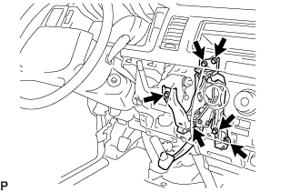
Using the 5 bolts and nut, temporarily install the brake pedal support assembly to the dash panel.
-
-
INSTALL ACCELERATOR PEDAL ROD ASSEMBLY
-
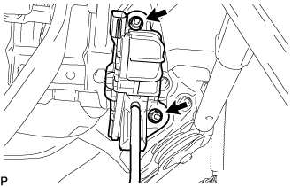
Install the accelerator pedal rod assembly with the 2 nuts.
- Torque:
- 5.0 N*m { 51 kgf*cm, 44 in.*lbf }
-
-
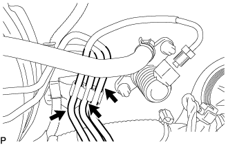
CONNECT WIRE HARNESS
-
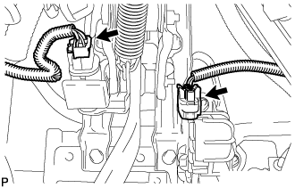
Connect the 2 connectors.
-
-
INSTALL BRAKE BOOSTER GASKET
-
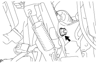
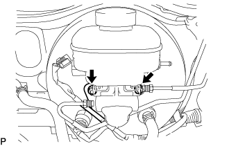
INSTALL BRAKE BOOSTER ASSEMBLY
-
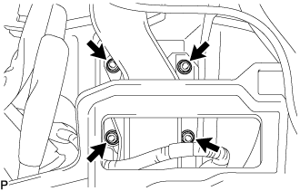
Install the brake booster assembly with the 4 nuts.
- Torque:
- 14 N*m { 145 kgf*cm, 10 ft.*lbf }
-
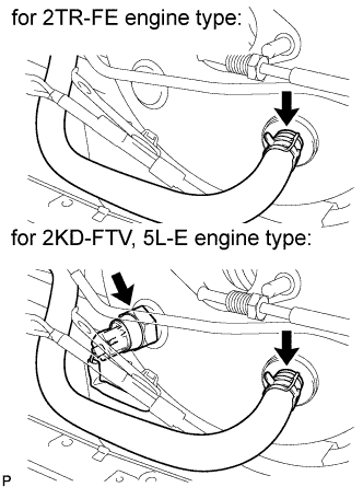
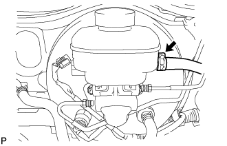
Connect the vacuum hose with the clip.
-
for 2KD-FTV, 5L-E engine type:
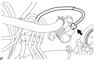
Connect the vacuum warning switch connector to the brake booster assembly.
-
-
FULLY TIGHTEN BRAKE PEDAL SUPPORT ASSEMBLY
-
Fully tighten the 5 bolts and nut.
- Torque:
- 31 N*m { 316 kgf*cm, 23 ft.*lbf }
-
Fully tighten the nut.
- Torque:
- 23 N*m { 239 kgf*cm, 17 ft.*lbf }
-
-
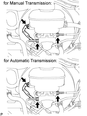
INSTALL BRAKE TUBE
-
for Automatic transmission:
Connect the 2 tubes to the clamp.
-
for Manual transmission:
-
Connect the 3 tubes to the clamp.
-
Using a union nut wrench, connect the clutch tube to the clutch master cylinder.
- Torque:
- 15 N*m { 155 kgf*cm, 11 ft.*lbf }
Note
Use the formula to calculate special torque values for situations where a union nut wrench is combined with a torque wrench Click here.
-
-
-
INSTALL MASTER CYLINDER PUSH ROD CLEVIS
-
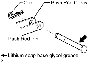
Apply a light coat of lithium soap base glycol grease to the clevis pin.
-
Install the push rod clevis to the brake pedal support assembly with the clevis pin and a new clip.
-
-
INSTALL INSTRUMENT PANEL FINISH PANEL LOWER
-
INSTALL WINDSHIELD WASHER JAR ASSEMBLY (for LHD with Standard Body)
-
INSTALL HEADLIGHT ASSEMBLY RH (for RHD with Standard Body)
Tech Tips
Install of the headlight assembly RH is the same as the headlight assembly LH.
-
for Halogen Headlight:
-
for LED Headlight:
-
-
INSTALL HEADLIGHT ASSEMBLY RH (for RHD with Wide Body)
Tech Tips
Install of the headlight assembly RH is the same as the headlight assembly LH.
-
for Halogen Headlight:
-
for LED Headlight:
-
-
INSTALL RADIATOR GRILLE (for LHD with Standard Body)
-
INSTALL BRAKE MASTER CYLINDER
Tech Tips
When installing the brake master cylinder, the brake booster push rod does not need to be adjusted.
-
Install the brake master cylinder and harness clamp bracket to the booster with the 2 nuts.
- Torque:
- 12.7 N*m { 130 kgf*cm, 9 ft.*lbf }
Note
Check that the stopper of the harness clamp bracket is securely holding on the brake master cylinder assembly.
-
for Manual Transmission:
Install the clutch reservoir tube with the clip.
-
Using a union nut wrench, connect the 2 brake tubes to the master cylinder.
- Torque:
- 15 N*m { 155 kgf*cm, 11 ft.*lbf }
Note
Use the formula to calculate special torque values for situations where a union nut wrench is combined with a torque wrench Click here.
-
Connect the level warning light switch connector.
-
-
ADD BRAKE FLUID
Fluid SAE J1703 or FMVSS No. 116 DOT3 or equivalent -
BLEED BRAKE MASTER CYLINDER
Tech Tips
If the master cylinder has been disassembled or if the reservoir becomes empty, bleed the air from the master cylinder.
-
Using a union nut wrench, disconnect the brake lines from the master cylinder.
-
Slowly depress the brake pedal and hold it there.
-
Block the outer holes with your fingers, and release the brake pedal.
-
Remove your fingers. Slowly depress the brake pedal and hold it again. Block the outer holes with your fingers and release the brake pedal. Repeat this procedure 3 or 4 times.
-
Using a union nut wrench, connect the brake lines to the master cylinder.
- Torque:
- 15 N*m { 155 kgf*cm, 11 ft.*lbf }
Note
Use the formula to calculate special torque values for situations where a union nut wrench is combined with a torque wrench Click here.
-
-
BLEED BRAKE LINE
-
Connect the vinyl tube to the bleeder plug.
-
Depress the brake pedal several times and loosen the bleeder plug with the pedal held down.
-
At the point where the fluid stops coming out, tighten the bleeder plug and release the brake pedal.
-
Repeat this procedure until the air in the brake fluid is completely bled out.
-
Tighten the bleeder plug.
-
Front bleeder plug:
- Torque:
- 10.8 N*m { 110 kgf*cm, 8 ft.*lbf }
-
Rear bleeder plug:
- Torque:
- 11.0 N*m { 112 kgf*cm, 8 ft.*lbf }
-
-
Repeat the above procedure to bleed the air out of the brake line for each wheel.
-
-
INSPECT BRAKE FLUID LEVEL
-
Check the fluid level and add fluid if necessary.
Fluid SAE J1703 or FMVSS No.116 DOT3 or equivalent
-
-
CHECK BRAKE FLUID LEAKAGE
-
VEHICLE PREPARATION FOR HEADLIGHT AIMING ADJUSTMENT
-
for Halogen Headlight:
-
for LED Headlight:
-
-
PREPARATION FOR HEADLIGHT AIMING (USING A SCREEN)
-
for Halogen Headlight:
-
for LED Headlight:
-
-
INSPECT HEADLIGHT AIMING
-
for Halogen Headlight:
-
for LED Headlight:
-
-
ADJUST HEADLIGHT AIMING
-
for Halogen Headlight:
-
for LED Headlight:
-
-
INSPECT BRAKE PEDAL HEIGHT
-
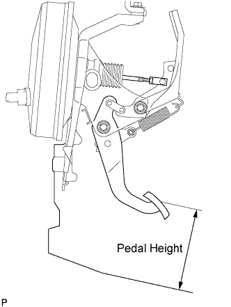
Check brake pedal height.
Pedal height from floor 151 to 161 mm (5.945 to 6.339 in.) for left hand drive 154 to 164 mm (6.063 to 6.457 in.) for right hand drive
-
-
ADJUST BRAKE PEDAL HEIGHT
-
Disconnect the stop light switch connector.
-
Turn the stop light switch assembly counter-clockwise and remove it.
-
Remove the brake booster Click here.
-
Loosen the push rod lock nut.
-
Adjust the pedal height by turning the pedal push rod clevis.
-
Tighten the push rod lock nut.
- Torque:
- 26 N*m { 260 kgf*cm, 19 ft.*lbf }
-
Install the brake booster Click here.
-
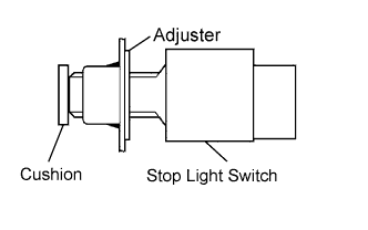
Insert the stop light switch into the adjuster until it slightly touches the cushion.
CAUTION:
Do not depress the brake pedal.
-
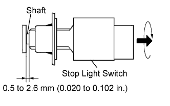
Turn the stop light switch assembly clockwise by approximately 90°.
CAUTION:
Do not depress the brake pedal.
-
Connect the stop light switch connector.
-
Check the clearance of the shaft.
Clearance 0.5 to 2.6 mm (0.020 to 0.102 in.)
-
-
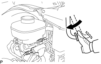
INSPECT BRAKE PEDAL FREE PLAY
-
Stop the engine and depress the brake pedal several times until there is no more vacuum left in the booster.
-
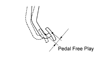
Push in the pedal until the beginning of the resistance is felt. Measure the distance as shown in the illustration.
Pedal free play 1.0 to 6.0 mm (0.039 to 0.236 in.)
-
-
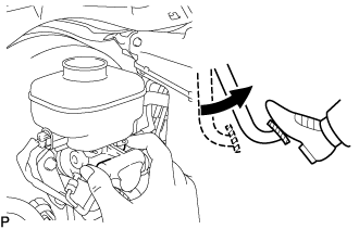
INSPECT BRAKE PEDAL RESERVE DISTANCE
-
Stop the engine and depress the brake pedal several times until there is no more vacuum left in the booster.
-
Release the parking brake handle.
-
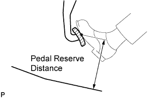
With the engine running, depress the pedal and measure the pedal reserve distance as shown in the illustration.
Pedal reserve distance from floor More than 117 mm (4.61 in.) at 500 N (51 kgf, 112.5 lbf) for left hand drive More than 120 mm (4.72 in.) at 500 N (51 kgf, 112.5 lbf) for right hand drive Note
Remove the floor mat before measuring the distance.
-