BLIND SPOT MONITOR SYSTEM Power Source Circuit
| DTC Code | DTC Name |
|---|---|
| Power Source Circuit |
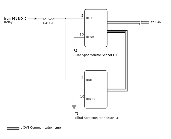
DESCRIPTION
This circuit provides power to operate the blind spot monitor sensor.
WIRING DIAGRAM
CAUTION / NOTICE / HINT
Inspect the fuses for circuits related to this system before performing the following inspection procedure.
PROCEDURE
CHECK HARNESS AND CONNECTOR (BLIND SPOT MONITOR SENSOR LH - AUXILIARY BATTERY)
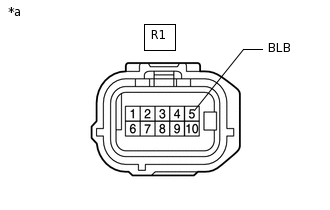
*a
Front view of wire harness connector
(to Blind Spot Monitor Sensor LH)
Disconnect the blind spot monitor sensor LH connector.
Measure the voltage according to the value(s) in the table below.
Standard Voltage
Tester Connection
Switch Condition
Specified Condition
R1-5 (BLB) - Body ground
Power switch on (IG)
11 to 14 V
R1-5 (BLB) - Body ground
Power switch off
Below 1 V
Result
Proceed to
OK
NG
NG REPAIR OR REPLACE HARNESS OR CONNECTOR
CHECK HARNESS AND CONNECTOR (BLIND SPOT MONITOR SENSOR LH - BODY GROUND)
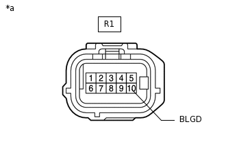
*a
Front view of wire harness connector
(to Blind Spot Monitor Sensor LH)
Disconnect the blind spot monitor sensor LH connector.
Measure the resistance according to the value(s) in the table below.
Standard Resistance
Tester Connection
Condition
Specified Condition
R1-10 (BLGD) - Body ground
Always
Below 1 Ω
Result
Proceed to
OK
NG
NG REPAIR OR REPLACE HARNESS OR CONNECTOR
CHECK HARNESS AND CONNECTOR (BLIND SPOT MONITOR SENSOR RH - AUXILIARY BATTERY)
-
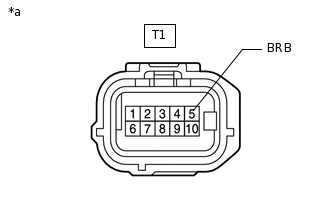
*a
Front view of wire harness connector
(to Blind Spot Monitor Sensor RH)
Disconnect the blind spot monitor sensor RH connector.
Measure the voltage according to the value(s) in the table below.
Standard Voltage
Tester Connection
Switch Condition
Specified Condition
T1-5 (BRB) - Body ground
Power switch on (IG)
11 to 14 V
T1-5 (BRB) - Body ground
Power switch off
Below 1 V
Result
Proceed to
OK
NG
NG REPAIR OR REPLACE HARNESS OR CONNECTOR
-
CHECK HARNESS AND CONNECTOR (BLIND SPOT MONITOR SENSOR RH - BODY GROUND)
-

*a
Front view of wire harness connector
(to Blind Spot Monitor Sensor RH)
Disconnect the blind spot monitor sensor RH connector.
Measure the resistance according to the value(s) in the table below.
Standard Resistance
Tester Connection
Condition
Specified Condition
T1-10 (BRGD) - Body ground
Always
Below 1 Ω
Result
Proceed to
OK
NG
NG REPAIR OR REPLACE HARNESS OR CONNECTOR
-