COMBINATION METER REMOVAL

-
PRECAUTION
Note
After turning the power switch off, waiting time may be required before disconnecting the cable from the auxiliary battery negative (-) terminal. Therefore, make sure to read the disconnecting the cable from the auxiliary battery negative (-) terminal notices before proceeding with work Click here.
-
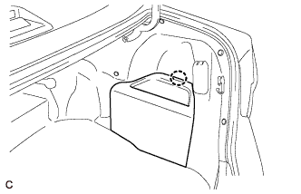
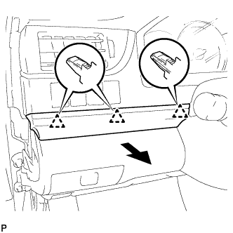
REMOVE LUGGAGE TRIM SERVICE HOLE COVER
-
Disengage the claw to remove the luggage trim service hole cover.
-
-
DISCONNECT CABLE FROM AUXILIARY BATTERY NEGATIVE TERMINAL
Note
When disconnecting the cable, some systems need to be initialized after the cable is reconnected Click here.
-
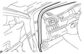
DISCONNECT FRONT DOOR OPENING TRIM WEATHERSTRIP LH
-
Disconnect the front door opening trim weatherstrip LH.
-
-
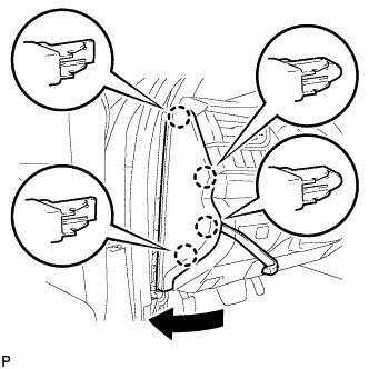
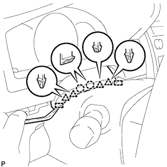
REMOVE INSTRUMENT SIDE PANEL LH
-
Using a moulding remover, disengage the 4 claws as shown in the illustration.
-
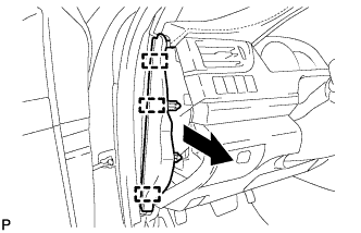
Disengage the 3 guides and remove the instrument side panel LH as shown in the illustration.
-
-
REMOVE NO. 1 INSTRUMENT CLUSTER FINISH PANEL GARNISH
-
Disengage the 3 clips to remove the No. 1 instrument cluster finish panel garnish as shown in the illustration.
-
-
REMOVE NO. 1 INSTRUMENT PANEL REGISTER ASSEMBLY
-
Apply protective tape to the area shown in the illustration.
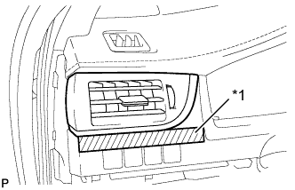
Text in Illustration *1 Protective Tape -
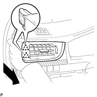
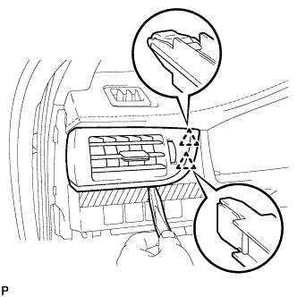
Disengage the 2 clips as shown in the illustration.
-
Using a moulding remover, disengage the 2 clips to remove the No. 1 instrument panel register assembly.
-
-
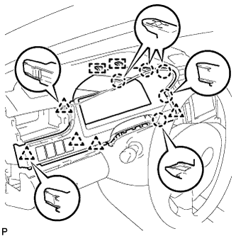
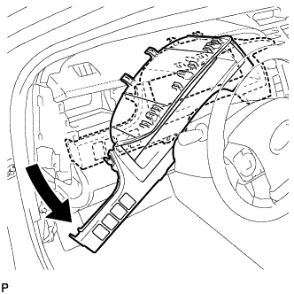
REMOVE INSTRUMENT CLUSTER FINISH PANEL ASSEMBLY
-
Operate the tilt and telescopic lever to fully extend and lower the steering column assembly.
-
Using a moulding remover, disengage the 2 claws, 4 clips and 2 guides.
-
Disengage the 5 claws, 5 clips and 2 guides.
-
Disconnect each connector.
-
Remove the instrument cluster finish panel assembly as shown in the illustration.
-
-
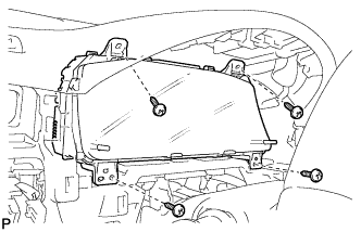
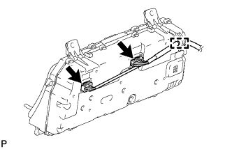
REMOVE COMBINATION METER ASSEMBLY
-
Remove the 4 screws.
-
Disengage the wire harness clamp.
-
Disconnect the 2 connectors to remove the combination meter assembly.
-