SAFETY CONNECT SYSTEM, Diagnostic DTC:B15C4

| DTC Code | DTC Name |
|---|---|
| B15C4 | Airbag Signal Malfunction/Not Input |
DESCRIPTION
If the DCM (Telematics Transceiver) detects an error in communication between the DCM (Telematics Transceiver) and the airbag sensor assembly as a result of the DCM (Telematics Transceiver) self check, this DTC will be set.
| DTC No. | DTC Detection Condition | Trouble Area |
|---|---|---|
| B15C4 | DCM (Telematics Transceiver) detects an error in signals from airbag sensor assembly when power switch is on (IG). |
|
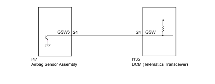
WIRING DIAGRAM
INSPECTION PROCEDURE
PROCEDURE
-
CHECK DTC (AIRBAG SYSTEM)
-
Turn the power switch off.
-
Connect the Techstream to the DLC3.
-
Turn the power switch on (IG) and wait for 10 seconds.
-
Turn the Techstream on.
-
Check the DTC of "Airbag System" Click here.
Result Result Proceed to DTC is not output A DTC is output B
B 
GO TO AIRBAG SYSTEM Click here
A 
-
-
INSPECT DCM (TELEMATICS TRANSCEIVER) (GSW SIGNAL)
-
Remove the DCM (Telematics Transceiver) but do not disconnect the connectors Click here.
-
Measure the voltage according to the value(s) in the table below.
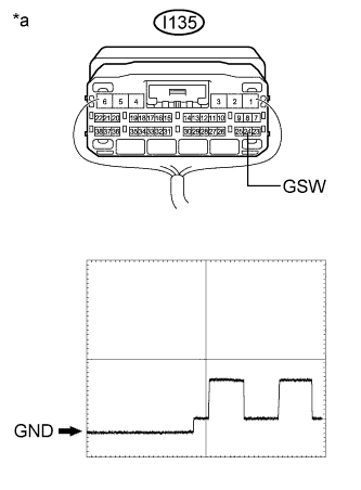
Standard Voltage Tester Connection Condition Specified Condition I135-24 (GSW) - Body ground Power switch on (IG) 6.5 to 8.5 V Text in Illustration *a Component with harness connected
(DCM (Telematics Transceiver))
Reference Waveform Item Condition Tester connection I135-24 (GSW) - Body ground Tool setting 5.0 V/DIV., 20 ms/DIV. Vehicle condition Power switch on (IG) Result Result Proceed to 8.5 V or higher A Below 6.5 V B 6.5 to 8.5 V C
B 
CHECK HARNESS AND CONNECTOR (FOR SHORT CIRCUIT) Click here
C
REPLACE DCM (TELEMATICS TRANSCEIVER) Click here
A
-
-
CHECK HARNESS AND CONNECTOR (FOR OPEN CIRCUIT)
-
Remove the airbag sensor assembly but do not disconnect the connectors Click here.
-
Measure the voltage according to the value(s) in the table below.
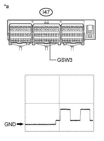
Standard Voltage Tester Connection Condition Specified Condition I47-24 (GSW3) - Body ground Power switch on (IG) 8.5 V or higher Text in Illustration *a Component with harness connected
(Airbag Sensor Assembly)
Reference Waveform Item Condition Tester connection I47-24 (GSW3) - Body ground Tool setting 5.0 V/DIV., 20 ms/DIV. Vehicle condition Power switch on (IG)
NG
REPAIR OR REPLACE HARNESS OR CONNECTOR
OK 
REPLACE AIRBAG SENSOR ASSEMBLY Click here
-
-
CHECK HARNESS AND CONNECTOR (FOR SHORT CIRCUIT)
-
Disconnect the I135 DCM (Telematics Transceiver) connector.
-
Measure the resistance according to the value(s) in the table below.
Standard Resistance Tester Connection Condition Specified Condition I135-24 (GSW) - Body ground Always 10 kΩ or higher
NG
CHECK HARNESS AND CONNECTOR (DCM (TELEMATICS TRANSCEIVER) - AIRBAG SENSOR ASSEMBLY) Click here
OK
-
-
REPLACE DCM (TELEMATICS TRANSCEIVER)
-
Replace the DCM (Telematics Transceiver) Click here.
Note
-
The power switch must be off.
-
Do not swap the DCM (Telematics Transceiver) with one from another vehicle.
-
NEXT
PERFORM DCM ACTIVATION Click here
-
-
CHECK HARNESS AND CONNECTOR (DCM (TELEMATICS TRANSCEIVER) - AIRBAG SENSOR ASSEMBLY)
-
Disconnect the I135 DCM (Telematics Transceiver) connector.
-
Disconnect the I47 airbag sensor assembly connector.
-
Measure the resistance according to the value(s) in the table below.
Standard Resistance Tester Connection Condition Specified Condition I135-24 (GSW) - I47-24 (GSW3) Always Below 1 Ω I135-24 (GSW) - Body ground Always 10 kΩ or higher
NG
REPAIR OR REPLACE HARNESS OR CONNECTOR
OK
REPLACE AIRBAG SENSOR ASSEMBLY Click here
-