CLEARANCE SONAR MAIN SWITCH INSTALLATION

-
INSTALL BACK SONAR OR CLEARANCE SONAR SWITCH ASSEMBLY
-
Engage the 2 claws to install the back sonar or clearance sonar switch assembly.
-
-
INSTALL INSTRUMENT CLUSTER FINISH PANEL ASSEMBLY
-
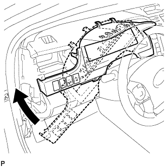
Temporarily install the instrument cluster finish panel assembly as shown in the illustration.
-
Connect each connector.
-
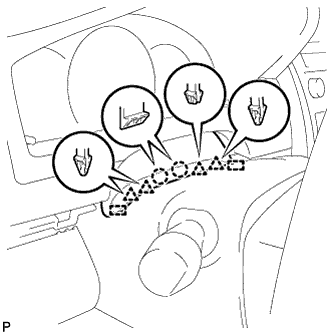
Engage the 5 claws, 5 clips and 2 guides, and install the instrument cluster finish panel assembly.
-
Engage the 2 claws, 4 clips and 2 guides.
-
-
INSTALL NO. 1 INSTRUMENT PANEL REGISTER ASSEMBLY
-
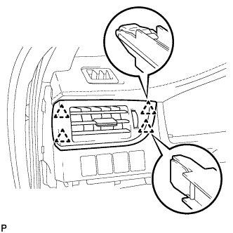
Engage the 4 clips to install the No. 1 instrument panel register assembly.
-
-
INSTALL NO. 1 INSTRUMENT CLUSTER FINISH PANEL GARNISH
-
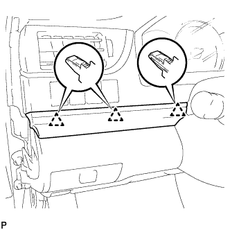
Engage the 3 clips to install the No. 1 instrument cluster finish panel garnish.
-
-
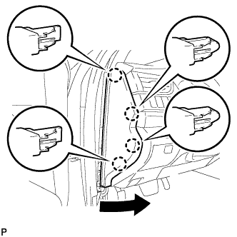
INSTALL INSTRUMENT SIDE PANEL LH
-
Engage the 3 guides.
-
Engage the 4 claws to install the instrument side panel LH as shown in the illustration.
-
-
INSTALL FRONT DOOR OPENING TRIM WEATHERSTRIP LH
-
Align the alignment mark (Yellow) on the weatherstrip with the protruding portion on the body indicated by the arrow in the illustration, and install the front door opening trim weatherstrip LH.
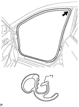
Text in Illustration *1 Alignment Mark (Yellow) Note
After installation, check that the corners fit correctly.
-