CLEARANCE SONAR MAIN SWITCH INSPECTION

-
INSPECT BACK SONAR OR CLEARANCE SONAR SWITCH ASSEMBLY
-
Measure the resistance according to the value(s) in the table below.
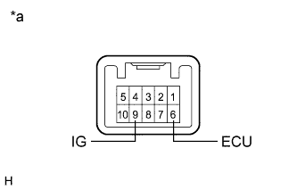
Standard Resistance Tester Connection Switch Condition Specified Condition 9 (IG) - 6 (ECU) Clearance sonar main switch on Below 1 Ω 9 (IG) - 6 (ECU) Clearance sonar main switch off 10 kΩ or higher Text in Illustration *a Component without harness connected
(Back Sonar or Clearance Sonar Switch Assembly)
If the result is not as specified, replace the back sonar or clearance sonar switch assembly.
-
Check that the switch illuminates.
-
Apply auxiliary battery voltage to the back sonar or clearance sonar switch assembly and check that the switch illuminates.
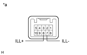
OK Tester Connection Specified Condition Auxiliary battery positive (+) → Terminal 8 (ILL+)
Auxiliary battery negative (-) → Terminal 7 (ILL-)
Illuminates Text in Illustration *a Component without harness connected
(Back Sonar or Clearance Sonar Switch Assembly)
If the result is not as specified, replace the back sonar or clearance sonar switch assembly.
-
-
Check switch indicator operation.
-
Apply auxiliary battery voltage to the back sonar or clearance sonar switch assembly and check that the switch indicator illuminates.
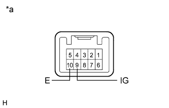
OK Tester Connection Switch Condition Specified Condition Auxiliary battery positive (+) → Terminal 9 (IG)
Auxiliary battery negative (-) → Terminal 10 (E)
Clearance sonar main switch on Indicator Illuminates Text in Illustration *a Component without harness connected
(Back Sonar or Clearance Sonar Switch Assembly)
If the result is not as specified, replace the back sonar or clearance sonar switch assembly.
-
-