NAVIGATION SYSTEM (for Radio and Display Type) Reverse Signal Circuit
DESCRIPTION
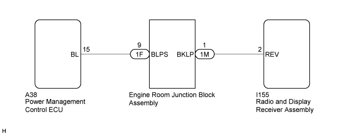
The radio and display receiver assembly receives a reverse signal from the power management control ECU via the engine room junction block assembly.
WIRING DIAGRAM
INSPECTION PROCEDURE
PROCEDURE
-
INSPECT RADIO AND DISPLAY RECEIVER ASSEMBLY
-
Disconnect the radio and display receiver assembly connector.
-
Measure the voltage according to the value(s) in the table below.
Standard Voltage Tester Connection Condition Specified Condition I155-2 (REV) - Body ground Power switch on (IG)
Shift lever in R
11 to 14 V I155-2 (REV) - Body ground Power switch on (IG)
Shift lever in any position other than R
Below 1 V
NG 
CHECK HARNESS AND CONNECTOR (RADIO AND DISPLAY RECEIVER ASSEMBLY - ENGINE ROOM JUNCTION BLOCK ASSEMBLY) Click here
OK 
PROCEED TO NEXT SUSPECTED AREA SHOWN IN PROBLEM SYMPTOMS TABLE Click here
-
-
CHECK HARNESS AND CONNECTOR (RADIO AND DISPLAY RECEIVER ASSEMBLY - ENGINE ROOM JUNCTION BLOCK ASSEMBLY)
-
Disconnect the radio and display receiver assembly connector.
-
Disconnect the engine room junction block assembly connector.
-
Measure the resistance according to the value(s) in the table below.
Standard Resistance Tester Connection Condition Specified Condition I155-2 (REV) - 1M-1 (BKLP) Always Below 1 Ω I155-2 (REV) - Body ground Always 10 kΩ or higher
NG 
REPAIR OR REPLACE HARNESS OR CONNECTOR
OK 
-
-
CHECK HARNESS AND CONNECTOR (ENGINE ROOM JUNCTION BLOCK ASSEMBLY - POWER MANAGEMENT CONTROL ECU)
-
Disconnect the engine room junction block assembly connector.
-
Disconnect the power management control ECU connector.
-
Measure the resistance according to the value(s) in the table below.
Standard Resistance Tester Connection Condition Specified Condition 1F-9 (BLPS) - A38-15 (BL) Always Below 1 Ω 1F-9 (BLPS) - Body ground Always 10 kΩ or higher
NG
REPAIR OR REPLACE HARNESS OR CONNECTOR
OK
-
-
REPLACE ENGINE ROOM JUNCTION BLOCK ASSEMBLY
-
Replace the engine room junction block assembly with a new one or known good one Click here.
-
Check that the malfunction disappears.
OK Malfunction disappears.
NG
REPLACE POWER MANAGEMENT CONTROL ECU Click here
OK
END (ENGINE ROOM JUNCTION BLOCK ASSEMBLY WAS DEFECTIVE)
-