NAVIGATION SYSTEM (for Radio and Display Type) Speaker Circuit
DESCRIPTION
-
If there is a short in a speaker circuit, the radio and display receiver assembly detects it and stops output to the speakers.
-
Thus sound cannot be heard from the speakers even if there is no malfunction in the radio and display receiver assembly or speakers.
-
If a short is detected in a speaker circuit, no sound can be heard from the speakers.
for 6 Speakers:
-
If there is a short in a speaker circuit, the stereo component amplifier assembly detects it and stops output to the speakers.
-
Thus sound cannot be heard from the speakers even if there is no malfunction in the stereo component amplifier assembly, DCM (telematics transceiver)*1 or speakers.
-
If a short is detected in a speaker circuit, no sound can be heard from the speakers.
-
*1: w/ Manual (SOS) Switch
for 10 Speakers:
WIRING DIAGRAM
-
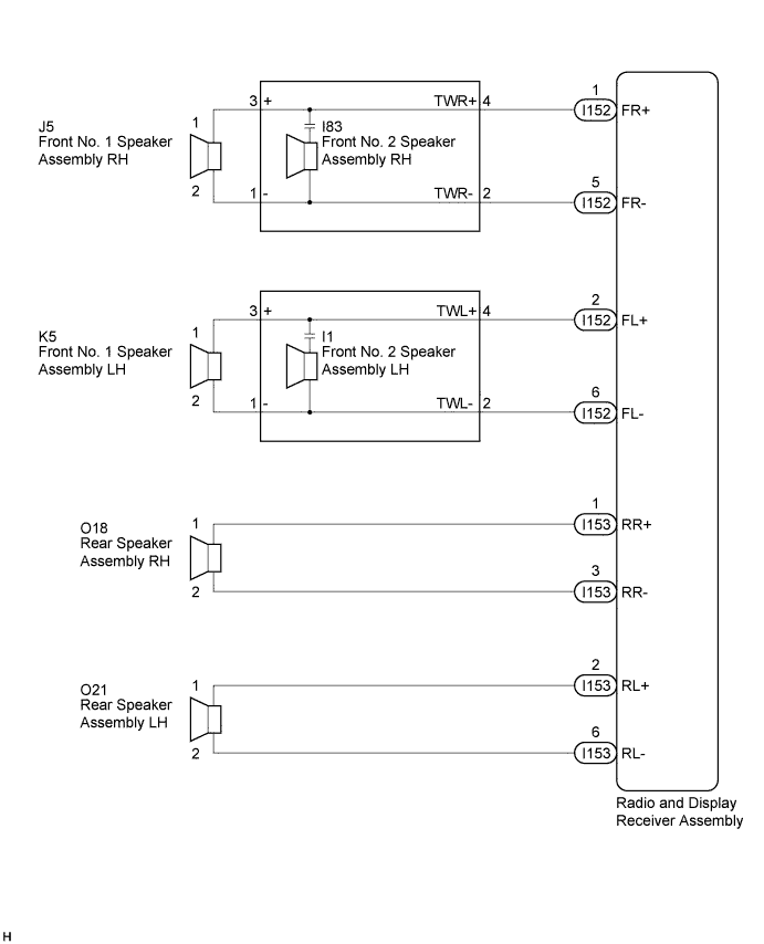
for 6 Speakers
-
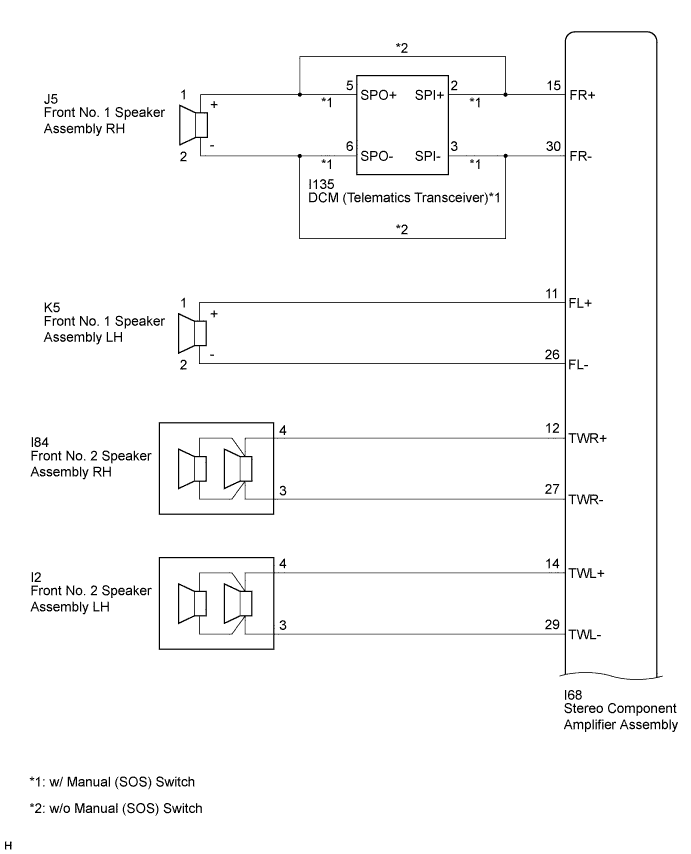
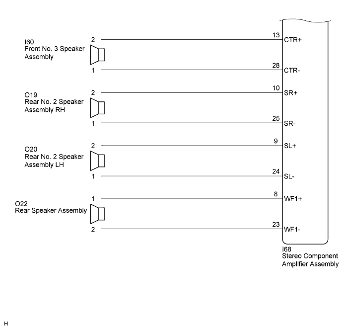
for 10 Speakers
INSPECTION PROCEDURE
PROCEDURE
-
CONFIRM MODEL
Result Result Proceed to for 6 Speakers A for 10 Speakers B B 
CHECK HARNESS AND CONNECTOR Click here
A 
-
CHECK HARNESS AND CONNECTOR
-
Disconnect the connectors from the radio and display receiver assembly and speakers.
-
Measure the resistance between each of the front No. 2 speaker assemblies and the radio and display receiver assembly to check for an open circuit in the wire harness.
Standard Resistance Tester Connection Condition Specified Condition I152-1 (FR+) - I83-4 (TWR+) Always Below 1 Ω I152-5 (FR-) - I84-2 (TWR-) Always Below 1 Ω I152-2 (FL+) - I1-4 (TWL+) Always Below 1 Ω I152-6 (FL-) - I1-2 (TWL-) Always Below 1 Ω -
Measure the resistance between each of the front No. 1 speaker assemblies and the front No. 2 speaker assemblies to check for an open circuit in the wire harness.
Standard Resistance Tester Connection Condition Specified Condition I83-3 (+) - J5-1 Always Below 1 Ω I83-1 (-) - J5-2 Always Below 1 Ω I1-3 (+) - K5-1 Always Below 1 Ω I1-1 (-) - K5-2 Always Below 1 Ω -
Measure the resistance between each of the rear speaker assemblies and the radio and display receiver assembly to check for an open circuit in the wire harness.
Standard Resistance Tester Connection Condition Specified Condition I153-1 (RR+) - O18-1 Always Below 1 Ω I153-3 (RR-) - O18-2 Always Below 1 Ω I153-2 (RL+) - O21-1 Always Below 1 Ω I153-6 (RL-) - O21-2 Always Below 1 Ω -
Measure the resistance between the radio and display receiver assembly and body ground to check for a short circuit in the wire harness.
Standard Resistance Tester Connection Condition Specified Condition I152-1 (FR+) - Body ground Always 10 kΩ or higher I152-5 (FR-) - Body ground Always 10 kΩ or higher I152-2 (FL+) - Body ground Always 10 kΩ or higher I152-6 (FL-) - Body ground Always 10 kΩ or higher I153-1 (RR+) - Body ground Always 10 kΩ or higher I153-3 (RR-) - Body ground Always 10 kΩ or higher I153-2 (RL+) - Body ground Always 10 kΩ or higher I153-6 (RL-) - Body ground Always 10 kΩ or higher -
Measure the resistance between each of the front No. 2 speaker assemblies and body ground to check for a short circuit in the wire harness.
Standard Resistance Tester Connection Condition Specified Condition I83-3 (+) - Body ground Always 10 kΩ or higher I83-1 (-) - Body ground Always 10 kΩ or higher I1-3 (+) - Body ground Always 10 kΩ or higher I1-1 (-) - Body ground Always 10 kΩ or higher
NG 
REPAIR OR REPLACE HARNESS OR CONNECTOR
OK
-
-
INSPECT FRONT NO. 1 SPEAKER ASSEMBLY
-
Resistance check
-
Measure the resistance according to the value(s) in the table below.
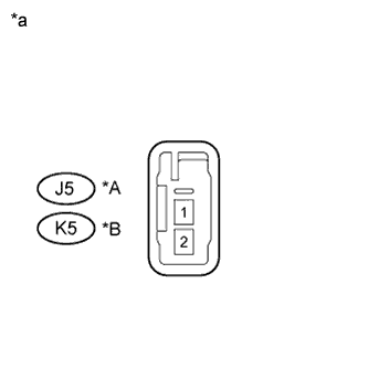
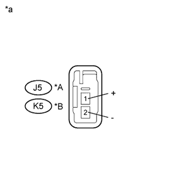
Standard Resistance Tester Connection Condition Specified Condition J5-1 - J5-2 Always 3.2 to 4.8 Ω K5-1 - K5-2 Always 3.2 to 4.8 Ω Text in Illustration *A for RH *B for LH *a Component without harness connected
(Front No. 1 Speaker Assembly)
-
NG
REPLACE FRONT NO. 1 SPEAKER ASSEMBLY Click here
OK
-
-
INSPECT FRONT NO. 2 SPEAKER ASSEMBLY
-
Resistance check
-
Measure the resistance according to the value(s) in the table below.
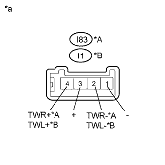
Standard Resistance Tester Connection Condition Specified Condition I83-2 (TWR-) - I83-4 (TWR+) Always 10 kΩ or higher I83-1 (-) - I83-2 (TWR-) Always Below 1 Ω I83-3 (+) - I83-4 (TWR+) Always Below 1 Ω I1-2 (TWL-) - I1-4 (TWL+) Always 10 kΩ or higher I1-1 (-) - I1-2 (TWL-) Always Below 1 Ω I1-3 (+) - I1-4 (TWL+) Always Below 1 Ω Text in Illustration *A for RH *B for LH *a Component without harness connected
(Front No. 2 Speaker Assembly)
-
NG
REPLACE FRONT NO. 2 SPEAKER ASSEMBLY Click here
OK
-
-
REPLACE FRONT NO. 2 SPEAKER ASSEMBLY
-
Check that the malfunction disappears when a known good speaker is installed Click here.
OK Malfunction disappears. Tech Tips
-
Connect all the connectors to the front No. 2 speaker assemblies that were disconnected.
-
When there is a possibility that either the right or left front speaker is defective, inspect by interchanging the right one with the left one.
-
Perform the above inspection on both LH and RH sides.
-
NG
INSPECT REAR SPEAKER ASSEMBLY Click here
OK 
END (FRONT NO. 2 SPEAKER ASSEMBLY WAS DEFECTIVE)
-
-
INSPECT REAR SPEAKER ASSEMBLY
-
Resistance check
-
Measure the resistance according to the value(s) in the table below.
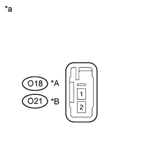
Standard Resistance Tester Connection Condition Specified Condition O18-1 - O18-2 Always 3.2 to 4.8 Ω O21-1 - O21-2 Always 3.2 to 4.8 Ω Text in Illustration *A for RH *B for LH *a Component without harness connected
(Rear Speaker Assembly)
-
NG
REPLACE REAR SPEAKER ASSEMBLY Click here
OK
PROCEED TO NEXT SUSPECTED AREA SHOWN IN PROBLEM SYMPTOMS TABLE Click here
-
-
CHECK HARNESS AND CONNECTOR
-
Disconnect the connectors from the stereo component amplifier assembly, DCM (telematics transceiver)*1 and speakers.
-
*1: w/ Manual (SOS) Switch
-
-
w/ Manual (SOS) Switch
Measure the resistance between the stereo component amplifier assembly and the DCM (telematics transceiver) to check for an open circuit in the wire harness.
Standard Resistance Tester Connection Condition Specified Condition I68-15 (FR+) - I135-2 (SPI+) Always Below 1 Ω I68-30 (FR-) - I135-3 (SPI-) Always Below 1 Ω -
w/ Manual (SOS) Switch
Measure the resistance between the front No. 1 speaker assembly RH and the DCM (telematics transceiver) to check for an open circuit in the wire harness.
Standard Resistance Tester Connection Condition Specified Condition J5-1 - I135-5 (SPO+) Always Below 1 Ω J5-2 - I135-6 (SPO-) Always Below 1 Ω -
w/o Manual (SOS) Switch
Measure the resistance between the front No. 1 speaker assembly RH and the stereo component amplifier assembly to check for an open circuit in the wire harness.
Standard Resistance Tester Connection Condition Specified Condition I68-15 (FR+) - J5-1 (+) Always Below 1 Ω I68-30 (FR-) - J5-2 (-) Always Below 1 Ω -
Measure the resistance between the front No. 1 speaker assembly LH and the stereo component amplifier assembly to check for an open circuit in the wire harness.
Standard Resistance Tester Connection Condition Specified Condition I68-11 (FL+) - K5-1 (+) Always Below 1 Ω I68-26 (FL-) - K5-2 (-) Always Below 1 Ω -
Measure the resistance between each of the front No. 2 speaker assemblies and the stereo component amplifier assembly to check for an open circuit in the wire harness.
Standard Resistance Tester Connection Condition Specified Condition I68-12 (TWR+) - I84-4 Always Below 1 Ω I68-27 (TWR-) - I84-3 Always Below 1 Ω I68-14 (TWL+) - I2-4 Always Below 1 Ω I68-29 (TWL-) - I2-3 Always Below 1 Ω -
Measure the resistance between the front No. 3 speaker assembly and the stereo component amplifier assembly to check for an open circuit in the wire harness.
Standard Resistance Tester Connection Condition Specified Condition I68-13 (CTR+) - I60-2 Always Below 1 Ω I68-28 (CTR-) - I60-1 Always Below 1 Ω -
Measure the resistance between each of the rear No. 2 speaker assemblies and the stereo component amplifier assembly to check for an open circuit in the wire harness.
Standard Resistance Tester Connection Condition Specified Condition I68-10 (SR+) - O19-2 Always Below 1 Ω I68-25 (SR-) - O19-1 Always Below 1 Ω I68-9 (SL+) - O20-2 Always Below 1 Ω I68-24 (SL-) - O20-1 Always Below 1 Ω -
Measure the resistance between the rear speaker assembly and the stereo component amplifier assembly to check for an open circuit in the wire harness.
Standard Resistance Tester Connection Condition Specified Condition I68-8 (WF1+) - O22-1 Always Below 1 Ω I68-23 (WF1-) - O22-2 Always Below 1 Ω -
Measure the resistance between the stereo component amplifier assembly and body ground to check for a short circuit in the wire harness.
Standard Resistance Tester Connection Condition Specified Condition I68-15 (FR+) - Body ground Always 10 kΩ or higher I68-30 (FR-) - Body ground Always 10 kΩ or higher I68-11 (FL+) - Body ground Always 10 kΩ or higher I68-26 (FL-) - Body ground Always 10 kΩ or higher I68-12 (TWR+) - Body ground Always 10 kΩ or higher I68-27 (TWR-) - Body ground Always 10 kΩ or higher I68-14 (TWL+) - Body ground Always 10 kΩ or higher I68-29 (TWL-) - Body ground Always 10 kΩ or higher I68-13 (CTR+) - Body ground Always 10 kΩ or higher I68-28 (CTR-) - Body ground Always 10 kΩ or higher I68-10 (SR+) - Body ground Always 10 kΩ or higher I68-25 (SR-) - Body ground Always 10 kΩ or higher I68-9 (SL+) - Body ground Always 10 kΩ or higher I68-24 (SL-) - Body ground Always 10 kΩ or higher I68-8 (WF1+) - Body ground Always 10 kΩ or higher I68-23 (WF1-) - Body ground Always 10 kΩ or higher -
w/ Manual (SOS) Switch
Measure the resistance between the DCM (telematics transceiver) and body ground to check for a short circuit in the wire harness.
Standard Resistance Tester Connection Condition Specified Condition I135-5 (SPO+) - Body ground Always 10 kΩ or higher I135-6 (SPO-) - Body ground Always 10 kΩ or higher
NG
REPAIR OR REPLACE HARNESS OR CONNECTOR
OK
-
-
INSPECT FRONT NO. 1 SPEAKER ASSEMBLY
-
Resistance check
-
Measure the resistance according to the value(s) in the table below.
Standard Resistance Tester Connection Condition Specified Condition J5-1 (+) - J5-2 (-) Always 4.6 to 6.6 Ω K5-1 (+) - K5-2 (-) Always 4.6 to 6.6 Ω Text in Illustration *A for RH *B for LH *a Component without harness connected
(Front No. 1 Speaker Assembly)
-
NG
REPLACE FRONT NO. 1 SPEAKER ASSEMBLY Click here
OK
-
-
INSPECT FRONT NO. 2 SPEAKER ASSEMBLY
-
Resistance check
-
Measure the resistance according to the value(s) in the table below.
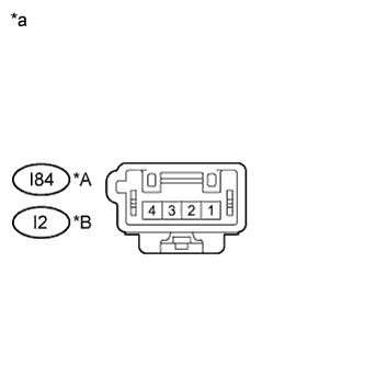
Standard Resistance Tester Connection Condition Specified Condition I84-4 - I84-3 Always 3.4 to 5.2 Ω I2-4 - I2-3 Always 3.4 to 5.2 Ω Text in Illustration *A for RH *B for LH *a Component without harness connected
(Front No. 2 Speaker Assembly)
-
NG
REPLACE FRONT NO. 2 SPEAKER ASSEMBLY Click here
OK
-
-
INSPECT FRONT NO. 3 SPEAKER ASSEMBLY
-
Resistance check
-
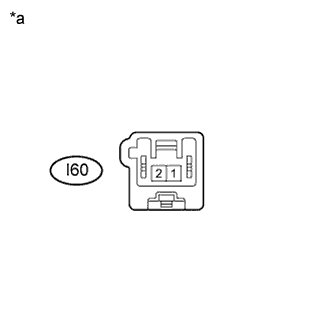
Measure the resistance according to the value(s) in the table below.
Standard Resistance Tester Connection Condition Specified Condition I60-1 - I60-2 Always 6.8 to 10.2 Ω Text in Illustration *a Component without harness connected
(Front No. 3 Speaker Assembly)
-
NG
REPLACE FRONT NO. 3 SPEAKER ASSEMBLY Click here
OK
-
-
INSPECT REAR NO. 2 SPEAKER ASSEMBLY
-
Resistance check
-
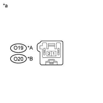
Measure the resistance according to the value(s) in the table below.
Standard Resistance Tester Connection Condition Specified Condition O19-1 - O19-2 Always 6.8 to 10.2 Ω O20-1 - O20-2 Always 6.8 to 10.2 Ω Text in Illustration *A for RH *B for LH *a Component without harness connected
(Rear No. 2 Speaker Assembly)
-
NG
REPLACE REAR NO. 2 SPEAKER ASSEMBLY Click here
OK
-
-
INSPECT REAR SPEAKER ASSEMBLY
-
Resistance check
-
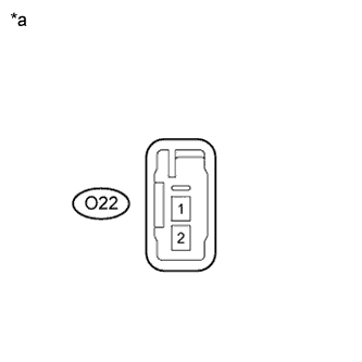
Measure the resistance according to the value(s) in the table below.
Standard Resistance Tester Connection Condition Specified Condition O22-1 - O22-2 Always 4.8 to 6.8 Ω Text in Illustration *a Component without harness connected
(Rear Speaker Assembly)
-
-
Proceed to the next step based on the inspection result.
Result Condition Proceed to OK (w/ Manual (SOS) Switch) A OK (w/o Manual (SOS) Switch) B NG C
B
PROCEED TO NEXT SUSPECTED AREA SHOWN IN PROBLEM SYMPTOMS TABLE Click here
C
REPLACE REAR SPEAKER ASSEMBLY Click here
A
-
-
INSPECT DCM (TELEMATICS TRANSCEIVER)
-
Resistance check
-
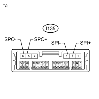
Measure the resistance according to the value(s) in the table below.
Standard Resistance Tester Connection Condition Specified Condition I135-2 (SPI+) - I135-5 (SPO+) Always Below 1 Ω I135-3 (SPI-) - I135-6 (SPO-) Always Below 1 Ω I135-2 (SPI+) - I135-3 (SPI-) Always 10 kΩ or higher I135-5 (SPO+) - I135-6 (SPO-) Always 10 kΩ or higher I135-2 (SPI+) - Body ground Always 10 kΩ or higher I135-3 (SPI-) - Body ground Always 10 kΩ or higher Text in Illustration *a Component without harness connected
(DCM (Telematics Transceiver))
-
NG
REPLACE DCM (TELEMATICS TRANSCEIVER) Click here
OK
PROCEED TO NEXT SUSPECTED AREA SHOWN IN PROBLEM SYMPTOMS TABLE Click here
-