NAVIGATION SYSTEM (for Radio and Display Type), Diagnostic DTC:B15C3

| DTC Code | DTC Name |
|---|---|
| B15C3 | Speaker Output Short |
DESCRIPTION
This DTC is stored when a malfunction occurs in the speakers.
| DTC No. | DTC Detection Condition | Trouble Area |
|---|---|---|
| B15C3 | A short is detected in the speaker output circuit. |
|
-
*1: w/ Manual (SOS) Switch
-
*2: for 10 Speakers
-
*3: for 6 Speakers
WIRING DIAGRAM
-
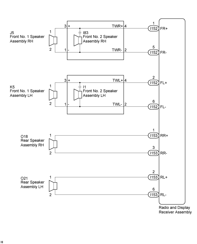
for 6 Speakers
-
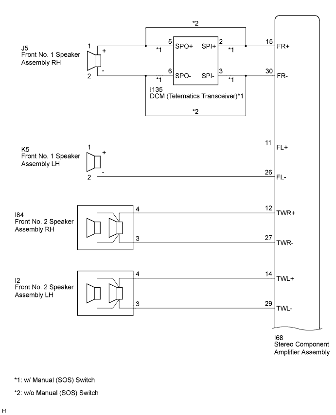
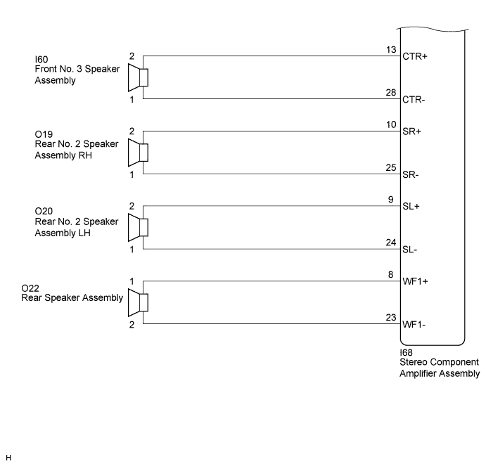
for 10 Speakers
INSPECTION PROCEDURE
Note
After replacing the radio and display receiver assembly of vehicles subscribed to pay-type satellite radio broadcasts, XM radio ID registration is necessary (w/ SDARS System).
PROCEDURE
-
CONFIRM MODEL
Result Result Proceed to for 6 Speakers A for 10 Speakers B B 
CHECK HARNESS AND CONNECTOR Click here
A 
-
CHECK HARNESS AND CONNECTOR
-
Disconnect the connectors from the radio and display receiver assembly and speakers.
-
Measure the resistance between the radio and display receiver assembly and body ground to check for a short circuit in the wire harness.
Standard Resistance Tester Connection Condition Specified Condition I152-1 (FR+) - Body ground Always 10 kΩ or higher I152-5 (FR-) - Body ground Always 10 kΩ or higher I152-2 (FL+) - Body ground Always 10 kΩ or higher I152-6 (FL-) - Body ground Always 10 kΩ or higher I153-1 (RR+) - Body ground Always 10 kΩ or higher I153-3 (RR-) - Body ground Always 10 kΩ or higher I153-2 (RL+) - Body ground Always 10 kΩ or higher I153-6 (RL-) - Body ground Always 10 kΩ or higher -
Measure the resistance between each of the front No. 2 speaker assemblies and body ground to check for a short circuit in the wire harness.
Standard Resistance Tester Connection Condition Specified Condition I83-3 (+) - Body ground Always 10 kΩ or higher I83-1 (-) - Body ground Always 10 kΩ or higher I1-3 (+) - Body ground Always 10 kΩ or higher I1-1 (-) - Body ground Always 10 kΩ or higher
NG 
REPAIR OR REPLACE HARNESS OR CONNECTOR
OK
-
-
INSPECT FRONT NO. 1 SPEAKER ASSEMBLY
-
Resistance check
-
Measure the resistance according to the value(s) in the table below.
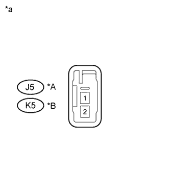
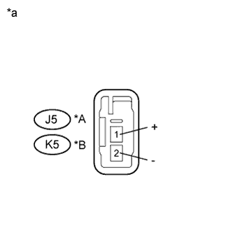
Standard Resistance Tester Connection Condition Specified Condition J5-1 - J5-2 Always 3.2 to 4.8 Ω K5-1 - K5-2 Always 3.2 to 4.8 Ω Text in Illustration *A for RH *B for LH *a Component without harness connected
(Front No. 1 Speaker Assembly)
-
NG
REPLACE FRONT NO. 1 SPEAKER ASSEMBLY Click here
OK
-
-
INSPECT FRONT NO. 2 SPEAKER ASSEMBLY
-
Resistance check
-
Measure the resistance according to the value(s) in the table below.
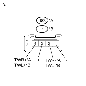
Standard Resistance Tester Connection Condition Specified Condition I83-2 (TWR-) - I83-4 (TWR+) Always 10 kΩ or higher I83-1 (-) - I83-2 (TWR-) Always Below 1 Ω I83-3 (+) - I83-4 (TWR+) Always Below 1 Ω I1-2 (TWL-) - I1-4 (TWL+) Always 10 kΩ or higher I1-1 (-) - I1-2 (TWL-) Always Below 1 Ω I1-3 (+) - I1-4 (TWL+) Always Below 1 Ω Text in Illustration *A for RH *B for LH *a Component without harness connected
(Front No. 2 Speaker Assembly)
-
NG
REPLACE FRONT NO. 2 SPEAKER ASSEMBLY Click here
OK
-
-
REPLACE FRONT NO. 2 SPEAKER ASSEMBLY
-
Check that the malfunction disappears when a known good speaker is installed Click here.
OK Malfunction disappears. Tech Tips
-
Connect all the connectors to the front No. 2 speaker assemblies that were disconnected.
-
When there is a possibility that either the right or left front speaker is defective, inspect by interchanging the right one with the left one.
-
Perform the above inspection on both LH and RH sides.
-
NG
INSPECT REAR SPEAKER ASSEMBLY Click here
OK 
END (FRONT NO. 2 SPEAKER ASSEMBLY WAS DEFECTIVE)
-
-
INSPECT REAR SPEAKER ASSEMBLY
-
Resistance check
-
Measure the resistance according to the value(s) in the table below.
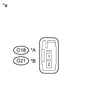
Standard Resistance Tester Connection Condition Specified Condition O18-1 - O18-2 Always 3.2 to 4.8 Ω O21-1 - O21-2 Always 3.2 to 4.8 Ω Text in Illustration *A for RH *B for LH *a Component without harness connected
(Rear Speaker Assembly)
-
NG
REPLACE REAR SPEAKER ASSEMBLY Click here
OK
REPLACE RADIO AND DISPLAY RECEIVER ASSEMBLY Click here
-
-
CHECK HARNESS AND CONNECTOR
-
Disconnect the connectors from the stereo component amplifier assembly, DCM (telematics transceiver)*1 and speakers.
-
*1: w/ Manual (SOS) Switch
-
-
Measure the resistance between the stereo component amplifier assembly and body ground to check for a short circuit in the wire harness.
Standard Resistance Tester Connection Condition Specified Condition I68-15 (FR+) - Body ground Always 10 kΩ or higher I68-30 (FR-) - Body ground Always 10 kΩ or higher I68-11 (FL+) - Body ground Always 10 kΩ or higher I68-26 (FL-) - Body ground Always 10 kΩ or higher I68-12 (TWR+) - Body ground Always 10 kΩ or higher I68-27 (TWR-) - Body ground Always 10 kΩ or higher I68-14 (TWL+) - Body ground Always 10 kΩ or higher I68-29 (TWL-) - Body ground Always 10 kΩ or higher I68-13 (CTR+) - Body ground Always 10 kΩ or higher I68-28 (CTR-) - Body ground Always 10 kΩ or higher I68-10 (SR+) - Body ground Always 10 kΩ or higher I68-25 (SR-) - Body ground Always 10 kΩ or higher I68-9 (SL+) - Body ground Always 10 kΩ or higher I68-24 (SL-) - Body ground Always 10 kΩ or higher I68-8 (WF1+) - Body ground Always 10 kΩ or higher I68-23 (WF1-) - Body ground Always 10 kΩ or higher -
w/ Manual (SOS) Switch
Measure the resistance between the DCM (telematics transceiver) and body ground to check for a short circuit in the wire harness.
Standard Resistance Tester Connection Condition Specified Condition I135-5 (SPO+) - Body ground Always 10 kΩ or higher I135-6 (SPO-) - Body ground Always 10 kΩ or higher
NG
REPAIR OR REPLACE HARNESS OR CONNECTOR
OK
-
-
INSPECT FRONT NO. 1 SPEAKER ASSEMBLY
-
Resistance check
-
Measure the resistance according to the value(s) in the table below.
Standard Resistance Tester Connection Condition Specified Condition J5-1 (+) - J5-2 (-) Always 4.6 to 6.6 Ω K5-1 (+) - K5-2 (-) Always 4.6 to 6.6 Ω Text in Illustration *A for RH *B for LH *a Component without harness connected
(Front No. 1 Speaker Assembly)
-
NG
REPLACE FRONT NO. 1 SPEAKER ASSEMBLY Click here
OK
-
-
INSPECT FRONT NO. 2 SPEAKER ASSEMBLY
-
Resistance check
-
Measure the resistance according to the value(s) in the table below.
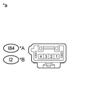
Standard Resistance Tester Connection Condition Specified Condition I84-4 - I84-3 Always 3.4 to 5.2 Ω I2-4 - I2-3 Always 3.4 to 5.2 Ω Text in Illustration *A for RH *B for LH *a Component without harness connected
(Front No. 2 Speaker Assembly)
-
NG
REPLACE FRONT NO. 2 SPEAKER ASSEMBLY Click here
OK
-
-
INSPECT FRONT NO. 3 SPEAKER ASSEMBLY
-
Resistance check
-
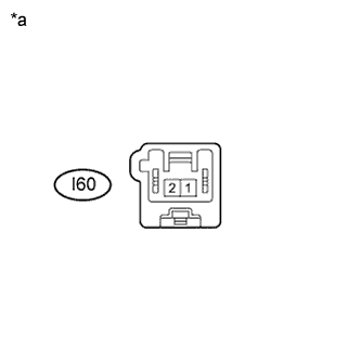
Measure the resistance according to the value(s) in the table below.
Standard Resistance Tester Connection Condition Specified Condition I60-1 - I60-2 Always 6.8 to 10.2 Ω Text in Illustration *a Component without harness connected
(Front No. 3 Speaker Assembly)
-
NG
REPLACE FRONT NO. 3 SPEAKER ASSEMBLY Click here
OK
-
-
INSPECT REAR NO. 2 SPEAKER ASSEMBLY
-
Resistance check
-
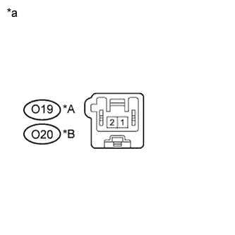
Measure the resistance according to the value(s) in the table below.
Standard Resistance Tester Connection Condition Specified Condition O19-1 - O19-2 Always 6.8 to 10.2 Ω O20-1 - O20-2 Always 6.8 to 10.2 Ω Text in Illustration *A for RH *B for LH *a Component without harness connected
(Rear No. 2 Speaker Assembly)
-
NG
REPLACE REAR SPEAKER ASSEMBLY Click here
OK
-
-
INSPECT REAR SPEAKER ASSEMBLY
-
Resistance check
-
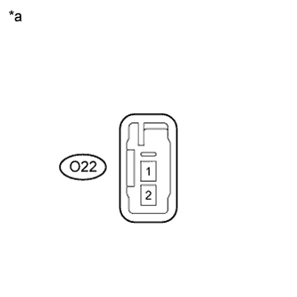
Measure the resistance according to the value(s) in the table below.
Standard Resistance Tester Connection Condition Specified Condition O22-1 - O22-2 Always 4.8 to 6.8 Ω Text in Illustration *a Component without harness connected
(Rear Speaker Assembly)
-
-
Proceed to the next step based on the inspection result.
Result Condition Proceed to OK (w/ Manual (SOS) Switch) A OK (w/o Manual (SOS) Switch) B NG C
B
REPLACE STEREO COMPONENT AMPLIFIER ASSEMBLY Click here
C
REPLACE REAR SPEAKER ASSEMBLY Click here
A
-
-
INSPECT DCM (TELEMATICS TRANSCEIVER)
-
Resistance check
-
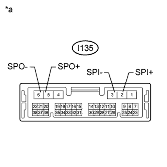
Measure the resistance according to the value(s) in the table below.
Standard Resistance Tester Connection Condition Specified Condition I135-2 (SPI+) - I135-5 (SPO+) Always Below 1 Ω I135-3 (SPI-) - I135-6 (SPO-) Always Below 1 Ω I135-2 (SPI+) - I135-3 (SPI-) Always 10 kΩ or higher I135-5 (SPO+) - I135-6 (SPO-) Always 10 kΩ or higher I135-2 (SPI+) - Body ground Always 10 kΩ or higher I135-3 (SPI-) - Body ground Always 10 kΩ or higher Text in Illustration *a Component without harness connected
(DCM (Telematics Transceiver))
-
NG
REPLACE DCM (TELEMATICS TRANSCEIVER) Click here
OK
REPLACE STEREO COMPONENT AMPLIFIER ASSEMBLY Click here
-