NAVIGATION SYSTEM (for Navigation Receiver Type), Diagnostic DTC:B1579

| DTC Code | DTC Name |
|---|---|
| B1579 | Voice Recognition Microphone Disconnected |
DESCRIPTION
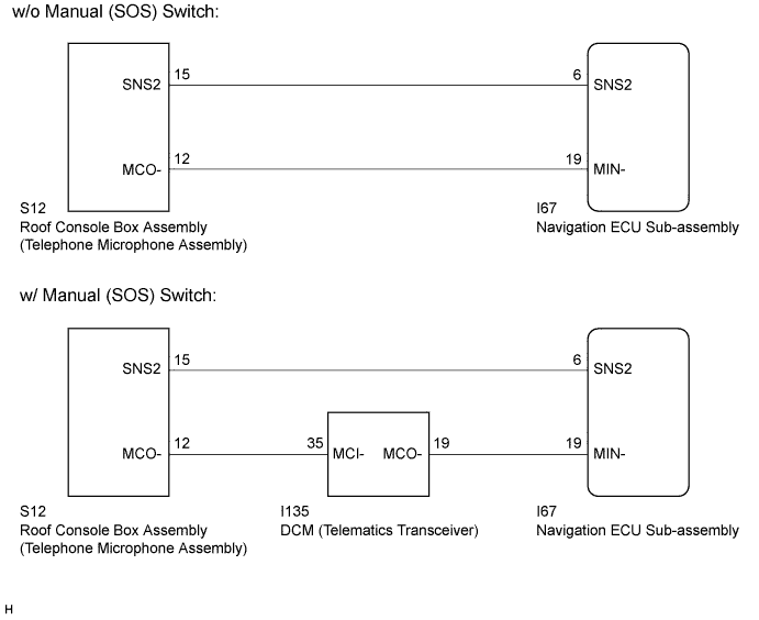
The navigation ECU sub-assembly and roof console box assembly (telephone microphone assembly) are connected to each other using the microphone connection detection signal lines.
This DTC is stored when a microphone connection detection signal line is disconnected.
| DTC Code | DTC Detection Condition | Trouble Area |
|---|---|---|
| B1579 | Telephone microphone signal is lost. |
|
-
*1: w/ Manual (SOS) Switch
WIRING DIAGRAM
INSPECTION PROCEDURE
Note
After replacing the navigation ECU sub-assembly of vehicles subscribed to pay-type satellite radio broadcasts, registration of the XM radio ID is necessary.
PROCEDURE
-
INSPECT NAVIGATION ECU SUB-ASSEMBLY
-
Measure the resistance according to the value(s) in the table below.
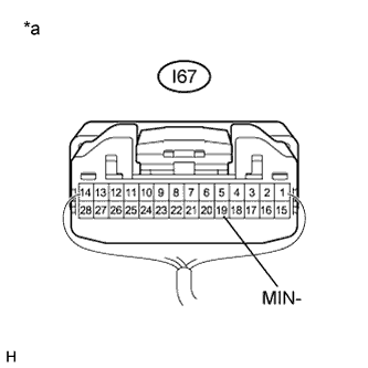
Standard Resistance Tester Connection Condition Specified Condition I67-19 (MIN-) - Body ground Always Below 1 Ω Text in Illustration *a Component with harness connected
(Navigation ECU Sub-assembly)
NG 
REPLACE NAVIGATION ECU SUB-ASSEMBLY Click here
OK 
-
-
CONFIRM MODEL
-
Choose the model to be inspected.
Result Model Proceed to w/ Manual (SOS) Switch A w/o Manual (SOS) Switch B
B 
CHECK HARNESS AND CONNECTOR (NAVIGATION ECU SUB-ASSEMBLY - ROOF CONSOLE BOX ASSEMBLY (TELEPHONE MICROPHONE ASSEMBLY)) Click here
A
-
-
CHECK HARNESS AND CONNECTOR (DCM (TELEMATICS TRANSCEIVER) - ROOF CONSOLE BOX ASSEMBLY (TELEPHONE MICROPHONE ASSEMBLY))
-
Disconnect the DCM (telematics transceiver) connector.
-
Disconnect the roof console box assembly (telephone microphone assembly) connector.
-
Measure the resistance according to the value(s) in the table below.
Standard Resistance Tester Connection Condition Specified Condition I135-35 (MCI-) - S12-12 (MCO-) Always Below 1 Ω I135-35 (MCI-) - Body ground Always 10 kΩ or higher
NG
REPAIR OR REPLACE HARNESS OR CONNECTOR
OK
-
-
CHECK HARNESS AND CONNECTOR (NAVIGATION ECU SUB-ASSEMBLY - DCM (TELEMATICS TRANSCEIVER))
-
Disconnect the navigation ECU sub-assembly connector.
-
Disconnect the DCM (telematics transceiver) connector.
-
Measure the resistance according to the value(s) in the table below.
Standard Resistance Tester Connection Condition Specified Condition I67-19 (MIN-) - I135-19 (MCO-) Always Below 1 Ω I67-19 (MIN-) - Body ground Always 10 kΩ or higher
NG
REPAIR OR REPLACE HARNESS OR CONNECTOR
OK
-
-
CHECK HARNESS AND CONNECTOR (NAVIGATION ECU SUB-ASSEMBLY - ROOF CONSOLE BOX ASSEMBLY (TELEPHONE MICROPHONE ASSEMBLY))
-
Disconnect the navigation ECU sub-assembly connector.
-
Disconnect the roof console box assembly (telephone microphone assembly) connector.
-
Measure the resistance according to the value(s) in the table below.
Standard Resistance Tester Connection Condition Specified Condition I67-6 (SNS2) - S12-15 (SNS2) Always Below 1 Ω I67-6 (SNS2) - Body ground Always 10 kΩ or higher
NG
REPAIR OR REPLACE HARNESS OR CONNECTOR
OK
-
-
INSPECT DCM (TELEMATICS TRANSCEIVER)
-
Reconnect the DCM (telematics transceiver) connector.
-
Reconnect the navigation ECU sub-assembly connector.
-
Measure the resistance according to the value(s) in the table below.
Standard Resistance Tester Connection Condition Specified Condition I135-35 (MCI-) - Body ground Always Below 1 Ω -
Proceed to the next step based on the inspection result.
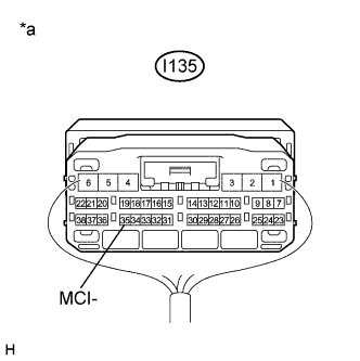
Result Result Proceed to NG A OK B Text in Illustration *a Component with harness connected
(DCM (Telematics Transceiver))
B
INSPECT ROOF CONSOLE BOX ASSEMBLY (TELEPHONE MICROPHONE ASSEMBLY) Click here
A 
REPLACE DCM (TELEMATICS TRANSCEIVER) Click here
-
-
CHECK HARNESS AND CONNECTOR (NAVIGATION ECU SUB-ASSEMBLY - ROOF CONSOLE BOX ASSEMBLY (TELEPHONE MICROPHONE ASSEMBLY))
-
Disconnect the navigation ECU sub-assembly connector.
-
Disconnect the roof console box assembly (telephone microphone assembly) connector.
-
Measure the resistance according to the value(s) in the table below.
Standard Resistance Tester Connection Condition Specified Condition I67-6 (SNS2) - S12-15 (SNS2) Always Below 1 Ω I67-19 (MIN-) - S12-12 (MCO-) Always Below 1 Ω I67-6 (SNS2) - Body ground Always 10 kΩ or higher I67-19 (MIN-) - Body ground Always 10 kΩ or higher
NG
REPAIR OR REPLACE HARNESS OR CONNECTOR
OK
-
-
INSPECT ROOF CONSOLE BOX ASSEMBLY (TELEPHONE MICROPHONE ASSEMBLY)
-
Measure the resistance according to the value(s) in the table below.
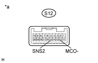
Standard Resistance Tester Connection Condition Specified Condition S12-15 (SNS2) - S12-12 (MCO-) Always Below 1 Ω Text in Illustration *a Component without harness connected
(Roof Console Box Assembly (Telephone Microphone Assembly))
NG
REPLACE ROOF CONSOLE BOX ASSEMBLY (TELEPHONE MICROPHONE ASSEMBLY) Click here
OK
REPLACE NAVIGATION ECU SUB-ASSEMBLY Click here
-