STEERING WHEEL INSTALLATION

Note
-
Do not replace the spiral cable with sensor sub-assembly with the auxiliary battery connected and the power switch on (IG).
-
Do not rotate the spiral cable with sensor sub-assembly without the steering wheel with the auxiliary battery connected and the power switch on (IG).
-
Ensure that the steering wheel is installed and aligned straight when inspecting the steering sensor.
-
INSTALL STEERING SHAKE DAMPER
-
Install the steering shake damper to the steering wheel sub-assembly with the 2 screws.
- Torque:
- 2.4 N*m { 24 kgf*cm, 21 in.*lbf }
-
-
INSTALL CRUISE CONTROL SWITCH WIRE
-
Install the cruise control switch wire.
-
-
INSTALL CRUISE CONTROL MAIN SWITCH
-
Connect the connector.
-
Install the cruise control switch main with the 2 screws shown in the illustration.
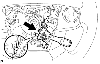
- Torque:
- 2.4 N*m { 24 kgf*cm, 21 in.*lbf }
-
-
INSTALL NO. 1 STEERING WHEEL ORNAMENT (w/o Steering Pad Switch RH)
-
Engage the claw and 2 pins to install the No. 1 steering wheel ornament to the steering wheel sub-assembly.
-
Install the 2 screws.
- Torque:
- 2.4 N*m { 24 kgf*cm, 21 in.*lbf }
-
-
INSTALL STEERING PAD SWITCH LH (w/o Steering Pad Switch RH)
-
Engage the claw and 2 pins to install the steering pad switch LH to the steering wheel sub-assembly.
-
Install the 2 screws.
- Torque:
- 2.4 N*m { 24 kgf*cm, 21 in.*lbf }
-
Connect the steering pad switch connector to the spiral cable sub-assembly.
-
Pass the wire harness over the guide.
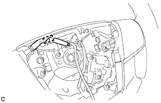
-
-
INSTALL STEERING PAD SWITCH ASSEMBLY (w/ Steering Pad Switch RH)
-
Engage the claw and 2 pins to install the steering pad switch assembly (RH side) to the steering wheel sub-assembly.
-
Install the 2 screws.
- Torque:
- 2.4 N*m { 24 kgf*cm, 21 in.*lbf }
-
Engage the claw and 2 pins to install the steering pad switch assembly (LH side) to the steering wheel sub-assembly.
-
Install the 2 screws.
- Torque:
- 2.4 N*m { 24 kgf*cm, 21 in.*lbf }
-
Connect the steering pad switch connector to the spiral cable sub-assembly.
-
Pass the wire harness over the 2 guides.
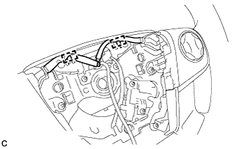
-
-
ALIGN FRONT WHEELS FACING STRAIGHT AHEAD
-
INSPECT AND ADJUST SPIRAL CABLE WITH SENSOR SUB-ASSEMBLY
Note
Do not adjust the spiral cable with sensor sub-assembly with the auxiliary battery connected and the power switch on (IG).
-
Check that the power switch is off.
-
Check that the cable is disconnected from the negative (-) auxiliary battery terminal.
CAUTION:
Wait at least 90 seconds after disconnecting the cable from the negative (-) auxiliary battery terminal to disable the SRS system.
-
Check if the spiral cable with sensor sub-assembly is centered.
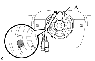
Text in Illustration 
Colored Part Tech Tips
When the spiral cable with sensor sub-assembly is centered, the part indicated by A is positioned at the top and the colored part shown in the illustration is visible.
-
If the spiral cable with sensor sub-assembly is not centered, center it.
-
While pushing on the interlock indicated in the illustration, rotate the spiral cable with sensor sub-assembly counterclockwise slowly by hand until it stops.
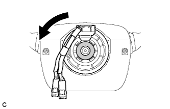
Text in Illustration 
Interlock Note
-
When rotating the spiral cable with sensor sub-assembly, make sure to push on the interlock indicated in the illustration to release the interlock mechanism.
-
Do not turn the spiral cable with sensor sub-assembly using the airbag wire harness.
-
-
Rotate the spiral cable with sensor sub-assembly clockwise approximately 2.5 turns to the position where the colored part shown in the illustration is visible.
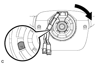
Text in Illustration Colored Part Interlock Tech Tips
The spiral cable with sensor sub-assembly will rotate approximately 2.5 turns to both the left and right from the center.
-
-
-
INSTALL STEERING WHEEL ASSEMBLY
-
Install the steering wheel assembly aligning the matchmarks on the steering wheel assembly and steering main shaft.
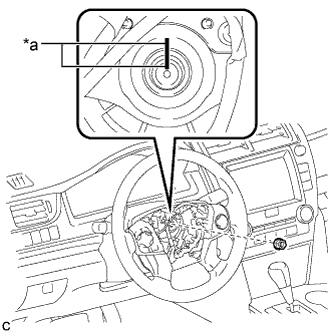
Text in Illustration *a Matchmark -
Install the steering wheel assembly set nut.
- Torque:
- 50 N*m { 510 kgf*cm, 37 ft.*lbf }
-
Connect the connectors to the spiral cable sub-assembly.
-
-
CHECK STEERING WHEEL CENTER POINT
-
INSTALL HORN BUTTON ASSEMBLY