POWER STEERING SYSTEM EPS Warning Light Circuit
DESCRIPTION
If the power steering ECU assembly detects a malfunction, the EPS warning light comes on. At this time, the power steering ECU assembly stores a DTC in its memory.
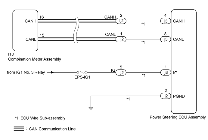
WIRING DIAGRAM
INSPECTION PROCEDURE
Note
If the power steering ECU assembly has been replaced, perform assist map writing Click here.
PROCEDURE
-
CHECK CONNECTOR CONNECTION CONDITION AND GROUND WIRE
-
Check the connection condition of the ECU wire sub-assembly and power steering ECU assembly connectors.
OK The ECU wire sub-assembly and power steering ECU assembly connectors are securely connected. -
Check that the ground wire is securely installed with the bolt Click here.
OK The ground wire is securely installed with the bolt.
NG 
CONNECT CONNECTOR OR INSTALL GROUND WIRE Click here
OK 
-
-
CHECK FOR DTC (CAN COMMUNICATION SYSTEM)
-
Check for DTCs Click here.
OK DTC is not output.
NG
GO TO CAN COMMUNICATION SYSTEM Click here
OK
-
-
CHECK HARNESS AND CONNECTOR (AUXILIARY BATTERY - ECU WIRE SUB-ASSEMBLY)
-
Disconnect the Ij2 connector from the ECU wire sub-assembly.
-
Measure the voltage according to the value(s) in the table below.
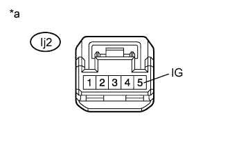
Standard Voltage Tester Connection Switch Condition Specified Condition Ij2-5 (IG) - Body ground Power switch on (IG) 9 to 16 V Text in Illustration *a Front view of wire harness connector
(to ECU Wire Sub-assembly)
NG
REPAIR OR REPLACE HARNESS OR CONNECTOR
OK
-
-
CHECK ECU WIRE SUB-ASSEMBLY
-
Connect the Ij2 connector to the ECU wire sub-assembly.
-
Disconnect the power steering ECU assembly j3 and j2 connectors.
-
Measure the voltage according to the value(s) in the table below.
Standard Voltage Tester Connection Switch Condition Specified Condition j3-1 (IG) - Body ground Power switch on (IG) 9 to 16 V -
Measure the resistance according to the value(s) in the table below.
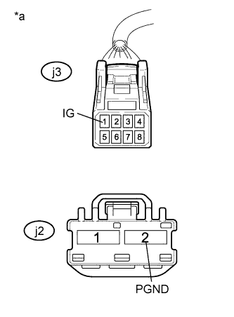
Standard Resistance Tester Connection Condition Specified Condition j2-2 (PGND) - Body ground Always Below 1 Ω Text in Illustration *a Front view of wire harness connector
(to Power Steering ECU Assembly)
NG
REPAIR OR REPLACE ECU WIRE SUB-ASSEMBLY Click here
OK
-
-
INSPECT COMBINATION METER ASSEMBLY
-
Reconnect the power steering ECU assembly connector.
-
Perform the Active Test of the combination meter assembly using the Techstream Click here.
-
Check the combination meter assembly.
OK The EPS warning light turns on or off in accordance with the Techstream operation. Tech Tips
If troubleshooting has been carried out according to Problem Symptoms Table, refer back to the table and proceed to the next step before replacing the part Click here.
NG
REPLACE COMBINATION METER ASSEMBLY Click here
OK 
REPLACE POWER STEERING ECU ASSEMBLY Click here
-