BRAKE PEDAL INSTALLATION

-
INSTALL BRAKE PEDAL SUPPORT ASSEMBLY
-
Install the brake pedal support assembly with the 4 nuts.
- Torque:
- 13 N*m { 131 kgf*cm, 9 ft.*lbf }
-
Engage the 3 clamps to install the wire harness to the brake pedal support assembly.
-
Engage the clamp.
-
-
INSTALL BRAKE PEDAL RETURN SPRING
-
Install the brake pedal return spring to the brake pedal support assembly.
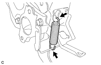
Note
Attach the bottom part of the brake pedal return spring first, making sure that the open part of the hook is facing the rear of the vehicle. Attach the top part of the brake pedal return spring second, making sure that the open part of the hook is facing the front of the vehicle.
-
-
INSTALL PUSH ROD PIN
-
Apply lithium soap base glycol grease to the push rod pin.
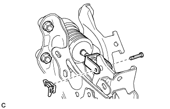
Text in Illustration 
Lithium Soap Base Glycol Grease -
Connect the brake master cylinder push rod clevis to the brake pedal support assembly with the push rod pin, and install a new clip as shown in the illustration.
Note
-
Be sure to insert the pin with its clip end facing the outside of the vehicle.
-
Make sure that the brake master cylinder push rod clevis moves sideway.
-
-
-
INSTALL STOP LIGHT SWITCH MOUNTING ADJUSTER
-
INSTALL STOP LIGHT SWITCH ASSEMBLY
-
Insert the stop light switch assembly until the threaded sleeve hits the pedal.
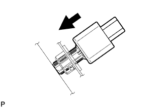
Note
When inserting the stop light switch assembly, support the pedal from behind so that the pedal is not pushed in.
-
Make a quarter turn clockwise to install the stop light switch assembly.
- Torque:
- 1.5 N*m { 15 kgf*cm, 13 in.*lbf, or less }
Note
When inserting the stop light switch assembly, support the pedal from behind so that the pedal is not pushed in.
-
Connect the connector.
-
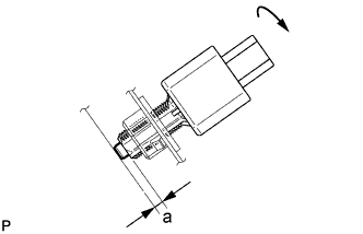
Check the protrusion of the plunger.
Protrusion of the plunger Area Measurement a 1.5 to 2.5 mm (0.0591 to 0.0984 in.) If the protrusion is not as specified, recheck switch installation and inspect brake pedal adjustment if necessary Click here.
Note
Do not depress or support the brake pedal.
-
-
INSTALL HEADLIGHT LEVELING ECU ASSEMBLY (w/ Automatic Headlight Beam Level Control System)
-
Engage the 2 guides.
-
Install the headlight leveling ECU assembly with the bolt.
- Torque:
- 8.0 N*m { 82 kgf*cm, 71 in.*lbf }
-
Engage the clamp.
-
Connect the connector.
-
-
INSTALL BRAKE PEDAL STROKE SENSOR ASSEMBLY
Note
-
Do not drop the brake pedal stroke sensor assembly.
-
If the brake pedal stroke sensor assembly has been dropped, replace the brake pedal stroke sensor assembly with a new one.
-
When installing a new brake pedal stroke sensor assembly:
Note
Do not break the brake pedal stroke sensor assembly lever set pin before installing the brake pedal stroke sensor assembly with the bolt.
-
Install a new brake pedal stroke sensor assembly to the brake pedal support assembly with the 2 bolts.
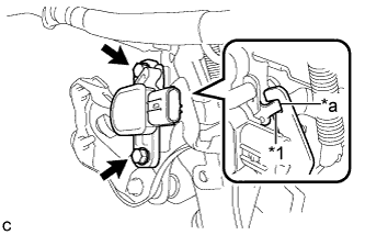
Text in Illustration *1 Brake Pedal Stroke Sensor Assembly Lever *a Brake Pedal Groove - Torque:
- 8.5 N*m { 87 kgf*cm, 75 in.*lbf }
Note
-
Engage the brake pedal stroke sensor assembly lever with the brake pedal groove.
-
Check that there is no foreign matter attached to the contact surface of the brake pedal stroke sensor assembly.
-
Check that the tip of the brake pedal stroke sensor assembly lever is protruding from the brake pedal groove.
-
Firmly depress the brake pedal and break the brake pedal stroke sensor assembly lever set pin.
-
Remove the broken lever set pin.
-
Connect the connector to the brake pedal stroke sensor assembly.
-
-
When reusing the brake pedal stroke sensor assembly:
-
Temporarily install the brake pedal stroke sensor assembly to the brake pedal support assembly with the 2 bolts.
Text in Illustration *1 Brake Pedal Stroke Sensor Assembly Lever *a Brake Pedal Groove Note
-
Engage the brake pedal stroke sensor assembly lever with the brake pedal groove.
-
Check that there is no foreign matter attached to the contact surface of the brake pedal stroke sensor assembly.
-
Check that the tip of the brake pedal stroke sensor assembly lever is protruding from the brake pedal groove.
Tech Tips
Fully tighten the 2 bolts when adjusting the brake pedal stroke sensor assembly.
-
-
Connect the connector to the brake pedal stroke sensor assembly.
-
-
-
INSTALL INSTRUMENT PANEL REINFORCEMENT ASSEMBLY WITH AIR CONDITIONING UNIT
-
INSPECT AND ADJUST BRAKE PEDAL