REAR SPEED SENSOR INSTALLATION

Tech Tips
-
Use the same procedure for the LH side and RH side.
-
The following procedure is for the LH side.
-
If the sensor rotor needs to be replaced, replace the rear axle hub and bearing assembly.
-
The rear speed sensor is a component of the rear axle hub and bearing assembly. If the rear speed sensor malfunctions, replace the rear axle hub and bearing assembly.
-
INSTALL REAR AXLE HUB AND BEARING ASSEMBLY
-
Install the rear axle hub and bearing assembly Click here.
Tech Tips
-
The rear speed sensor is a component of the rear axle hub and bearing assembly. If the sensor malfunctions, replace the rear axle hub and bearing assembly.
-
If the sensor rotor needs to be replaced, replace the rear axle hub and bearing assembly.
-
-
-
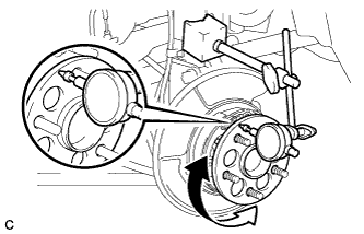
INSPECT REAR AXLE HUB BEARING LOOSENESS
-
Using a dial indicator, check for looseness near the center of the rear axle hub.
Maximum looseness 0.05 mm (0.00197 in.) Note
-
Ensure that the dial indicator is set perpendicular to the measurement surface.
-
Keep the magnet of the dial indicator away from the rear axle hub and bearing assembly.
If the looseness exceeds the maximum, replace the rear axle hub and bearing assembly.
-
-
-
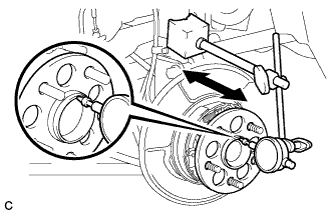
INSPECT REAR AXLE HUB RUNOUT
-
Using a dial indicator, check for runout on the surface of the rear axle hub outside the rear axle hub bolts.
Maximum runout 0.07 mm (0.00276 in.) Note
-
Ensure that the dial indicator is set perpendicular to the measurement surface.
-
Make sure to install the tip of the dial indicator towards the outside of the rear axle hub bolt.
-
Keep the magnet of the dial indicator away from the rear axle hub and bearing assembly.
If the runout exceeds the maximum, replace the rear axle hub and bearing assembly.
-
-
-
CONNECT SKID CONTROL SENSOR WIRE
-
Connect the connector to the rear axle hub and bearing assembly.
-
-
INSTALL REAR DISC
-
Align the matchmarks of the rear disc and rear axle hub, and install the rear disc.
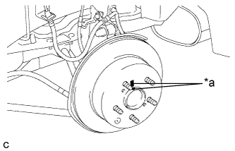
Text in Illustration *a Matchmark Note
When replacing the disc with a new one, select the installation position where the rear disc has minimal runout.
-
-
INSTALL PARKING BRAKE SHOE ADJUSTING HOLE PLUG
-
Install the parking brake shoe adjusting hole plug.
-
-
INSTALL REAR DISC BRAKE CALIPER ASSEMBLY
-
Install the rear disc brake caliper assembly with the 2 bolts.
- Torque:
- 78 N*m { 799 kgf*cm, 58 ft.*lbf }
-
Install the rear flexible hose to the rear shock absorber with the bolt.
- Torque:
- 19 N*m { 192 kgf*cm, 14 ft.*lbf }
-
-
CONNECT CABLE TO AUXILIARY BATTERY NEGATIVE TERMINAL
-
Connect the cable to the negative (-) auxiliary battery terminal Click here.
-
Connect the reservoir level switch connector.
-
Clear the DTCs Click here.
-
-
ADJUST PARKING BRAKE
-
INSTALL REAR WHEEL
- Torque:
- 103 N*m { 1049 kgf*cm, 76 ft.*lbf }
-
CHECK FOR SPEED SENSOR SIGNAL