FRONT SUSPENSION MEMBER REMOVAL

-
REMOVE FRONT FRAME ASSEMBLY
-
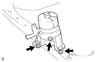
REMOVE FRONT ENGINE MOUNTING INSULATOR
-
Remove the 3 nuts and front engine mounting insulator.
Tech Tips
Perform this procedure only when replacement of the front engine mounting insulator is necessary.
-
-
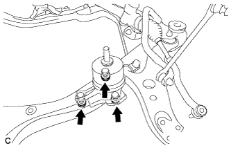
REMOVE ENGINE MOUNTING INSULATOR LH
-
Remove the 2 hole plugs from the front frame assembly.
-
Remove the 3 nuts and engine mounting insulator LH.
Tech Tips
Perform this procedure only when replacement of the engine mounting insulator LH is necessary.
-
-
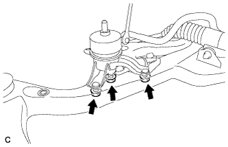
REMOVE ENGINE MOUNTING INSULATOR RH
-
Remove the 2 hole plugs from the front frame assembly.
-
Remove the 3 nuts and engine mounting insulator RH.
Tech Tips
Perform this procedure only when replacement of the engine mounting insulator RH is necessary.
-
-
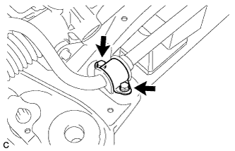
REMOVE FRONT NO. 1 STABILIZER BRACKET LH
-
Remove the 2 bolts and front No. 1 stabilizer bracket LH from the front frame assembly.
-
-
REMOVE FRONT NO. 1 STABILIZER BRACKET RH
Tech Tips
Perform the same procedure as the LH side.
-
REMOVE FRONT STABILIZER BAR WITH FRONT STABILIZER LINK ASSEMBLY
-
Remove the front stabilizer bar with 2 front stabilizer link assemblies from the front frame assembly.
-
-
REMOVE STEERING LINK ASSEMBLY
-
Remove the 2 bolts, 2 nuts and steering link assembly.
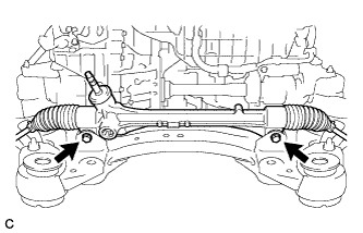
Note
Keep the nut from rotating while turning the bolt because the nut has its own stopper.
-
-
REMOVE FRONT LOWER NO. 1 SUSPENSION ARM SUB-ASSEMBLY LH
-
Remove the 3 bolts, nut and front lower No. 1 suspension arm sub-assembly from the front frame assembly.
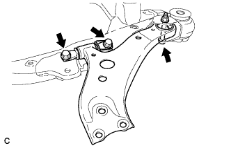
Note
When removing the bolt, keep the nut from rotating.
-
Remove the front lower arm bushing stopper from the front lower No. 1 suspension arm sub-assembly.
-
-
REMOVE FRONT LOWER NO. 1 SUSPENSION ARM SUB-ASSEMBLY RH
Tech Tips
Perform the same procedure as the LH side.
-
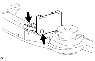
REMOVE FRONT SUSPENSION MEMBER DYNAMIC DAMPER
-
Remove the 2 bolts and front suspension member dynamic damper from the front frame assembly.
-
-
REMOVE FRONT SUSPENSION MEMBER BODY MOUNTING FRONT STOPPER
-
Remove the 2 front suspension member body mounting front stoppers from the front frame assembly.
-
-
REMOVE FRONT SUSPENSION MEMBER BODY MOUNTING REAR STOPPER
-
Remove the 2 front suspension member body mounting rear stoppers from the front frame assembly.
-
-
REMOVE FRONT SUSPENSION MEMBER BODY MOUNTING FRONT CUSHION
-
Install SST as shown in the illustration.
- SST
- 09830-10010 ( 09830-01010, 09830-01040, 09830-01050 )
- 09950-40011 ( 09951-04020, 09952-04010, 09954-04010, 09955-04011, 09958-04011 )
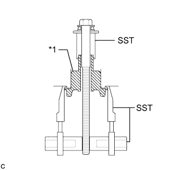
Text in Illustration *1 Front Suspension Member Body Mounting Front Cushion -
Using SST, remove the front suspension member body mounting front cushion from the front frame assembly.
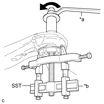
Text in Illustration *a Turn *b Hold Note
-
Make sure that the claws of SST are securely hung onto the mounting cushion.
-
Tighten SST slowly and evenly.
-
Be careful as the mounting cushion may fly out.
-
The mounting cushion cannot be reused.
-
-
-
REMOVE FRONT SUSPENSION MEMBER BODY MOUNTING REAR CUSHION LH
-
Install SST as shown in the illustration.
- SST
- 09830-10010 ( 09830-01010, 09830-01040, 09830-01050 )
- 09950-40011 ( 09951-04020, 09952-04010, 09954-04010, 09955-04011, 09958-04011 )
Text in Illustration *1 Front Suspension Member Body Mounting Rear Cushion LH -
Using SST, remove the front suspension member body mounting rear cushion LH from the front frame assembly.
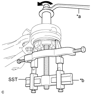
Text in Illustration *a Turn *b Hold Note
-
Make sure that the claws of SST are securely hung onto the mounting cushion.
-
Tighten SST slowly and evenly.
-
Be careful as the mounting cushion may fly out.
-
The mounting cushion cannot be reused.
-
-
-
REMOVE FRONT SUSPENSION MEMBER BODY MOUNTING REAR CUSHION RH
Tech Tips
Perform the same procedure as the LH side.
-
REMOVE HOLE PLUG
-
Remove each hole plug from the front frame assembly.
-