FRONT AXLE HUB REMOVAL

Note
When the brake pedal is first depressed after replacing the brake pads or pushing back the disc brake piston, DTC C1214 may be output. As there is no malfunction, clear the DTC.
Tech Tips
-
Use the same procedure for the RH side and LH side.
-
The procedure listed below is for the LH side.
-
PRECAUTION
Note
After turning the power switch off, waiting time may be required before disconnecting the cable from the negative (-) auxiliary battery terminal. Therefore, make sure to read the disconnecting the cable from the negative (-) auxiliary battery terminal notice before proceeding with work Click here.
-
DISABLE BRAKE CONTROL
-
Wait at least 2 minutes after turning the power switch off.
Note
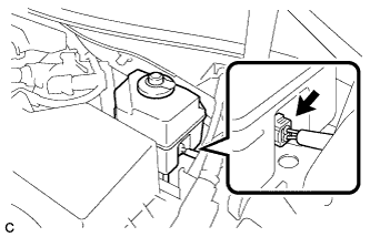
When the brake pedal is depressed or the door courtesy switch is turned on even if the power switch is off, the brake control system activates. Therefore do not depress the brake pedal or open/close the doors until the reservoir level switch connector is disconnected.
-
Disconnect the reservoir level switch connector with the parking brake applied.
-
Disconnect the cable from the negative (-) auxiliary battery terminal Click here.
-
Depress the brake pedal 40 times or more to return all the fluid in the accumulator back to the reservoir.
-
Check that the brake pedal can not be further depressed.
-
Release the parking brake.
-
-
REMOVE FRONT WHEEL
-
REMOVE FRONT AXLE SHAFT NUT
-
Using SST and a hammer, release the staked part of the front axle shaft nut.
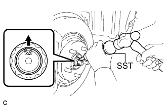
- SST
- 09930-00010
Note
Loosen the staked part of the nut completely, otherwise the threads of the drive shaft may be damaged.
-
While applying the brakes, remove the front axle shaft nut.
-
-
SEPARATE FRONT SPEED SENSOR
-
Remove the bolt, disengage the clamp and separate the front speed sensor and front flexible hose.
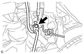
Note
Be sure to separate the front speed sensor from the front shock absorber completely.
-
Remove the bolt and front speed sensor from the steering knuckle.
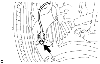
Note
-
Prevent foreign matter from contacting the sensor tip.
-
Be careful not to damage the front speed sensor.
-
Clean the speed sensor installation hole and the contact surfaces every time the speed sensor is removed.
-
-
-
SEPARATE FRONT DISC BRAKE CALIPER ASSEMBLY
-
Remove the 2 bolts and separate the front disc brake caliper assembly.
Note
Use wire or an equivalent tool to keep the front disc brake caliper assembly from hanging down by the front flexible hose.
-
-
REMOVE FRONT DISC
-
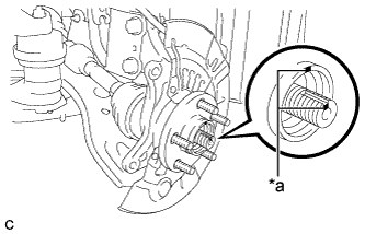
Put matchmarks on the front disc and the front axle hub.
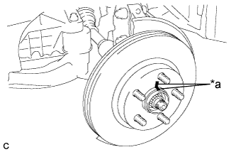
Text in Illustration *a Matchmark -
Remove the front disc.
-
-
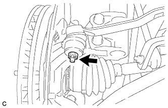
SEPARATE TIE ROD ASSEMBLY
-
Remove the cotter pin and nut.
-
Install SST to the tie rod assembly LH.
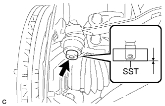
- SST
- 09960-20010 ( 09961-02060 )
Note
Make sure that the lower ends of the tie rod assembly LH and SST are aligned.
-
Secure SST using a string.
Note
Be sure to tighten the string firmly to secure SST to the steering knuckle to prevent SST from falling off.
-
Using SST, separate the tie rod assembly LH from the steering knuckle.
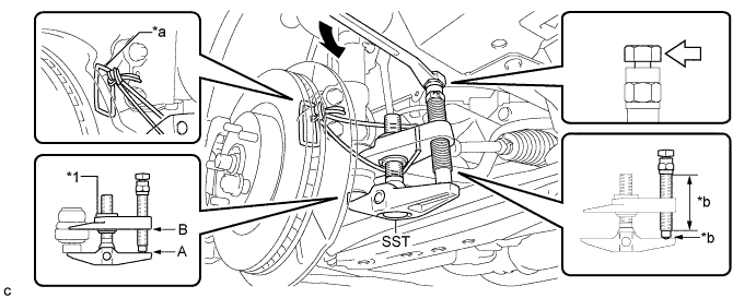
Text in Illustration *1 Center Nut - - *a String *b Grease Application Area 
Place the wrench here. - - - SST
- 09960-20010 ( 09961-02010 )
CAUTION:
Apply grease to the bolt threads and the tip of SST.
Note
-
Install SST with the center nut so that A and B shown in the illustration are parallel. Otherwise, the dust cover may be damaged.
-
Be sure to place the wrench on the part indicated in the illustration.
-
Do not damage the front disc brake dust cover.
-
Do not damage the ball joint dust cover.
-
Do not damage the steering knuckle.
-
-
SEPARATE FRONT DRIVE SHAFT ASSEMBLY
-
Put matchmarks on the front drive shaft assembly and the front axle hub sub-assembly.
Text in Illustration *a Matchmark -
Using a plastic hammer, separate the front drive shaft assembly from the front axle assembly.
If it is difficult to separate, tap the end of the front drive shaft assembly using a brass bar and a hammer.
-
-
SEPARATE FRONT LOWER NO. 1 SUSPENSION ARM SUB-ASSEMBLY
-
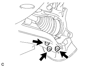
Remove the bolt and 2 nuts, and separate the front lower No. 1 suspension arm sub-assembly from the front lower ball joint assembly.
-
-
REMOVE FRONT AXLE ASSEMBLY
-
Remove the 2 bolts, 2 nuts and front axle assembly from the front shock absorber.
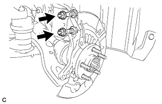
Note
-
When removing the nuts, keep the bolts from rotating.
-
Be careful not to damage the drive shaft boot or speed sensor rotor.
-
-
-
REMOVE FRONT NO. 1 WHEEL BEARING DUST DEFLECTOR
-
Using a screwdriver with its tip wrapped with vinyl tape, remove the front No. 1 wheel bearing dust deflector.
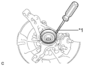
Text in Illustration *1 Vinyl Tape Note
Be careful not to damage the steering knuckle.
-
-
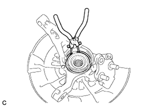
REMOVE FRONT AXLE HUB HOLE SNAP RING
-
Using snap ring pliers, remove the front axle hub hole snap ring.
-
-
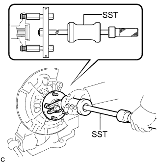
REMOVE FRONT AXLE HUB SUB-ASSEMBLY
-
Hold the front axle assembly between aluminum plates in a vise.
Note
Do not overtighten the vise.
-
Using SST, remove the front axle hub sub-assembly.
- SST
- 09520-00031
-
Using SST and a press, remove the bearing inner race (outside) from the front axle hub sub-assembly.
- SST
- 09555-55010
- 09950-60010 ( 09951-00440 )
- 09950-70010 ( 09951-07100 )
Note
Be careful not to drop the front axle hub sub-assembly.
-
-
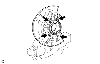
REMOVE FRONT DISC BRAKE DUST COVER
-
Remove the 4 bolts and front disc brake dust cover from the steering knuckle.
-
-
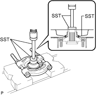
REMOVE FRONT AXLE HUB BEARING
-
Place the bearing inner race (outside) on the front axle hub bearing.
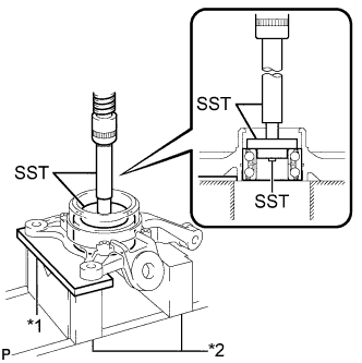
Text in Illustration *1 Steel Plate *2 V-block -
Using SST, a steel plate, V-blocks and a press, remove the front axle hub bearing from the steering knuckle.
- SST
- 09950-60010 ( 09951-00440, 09952-06010 )
- 09950-60020 ( 09951-00750 )
- 09950-70010 ( 09951-07100 )
Note
Keep the steering knuckle level.
-