SHIFT LEVER POSITION SENSOR INSTALLATION

-
INSTALL SHIFT LEVER POSITION SENSOR
-
Install the shift lever position sensor to the manual valve shaft.
-
Temporarily install the 2 bolts.
-
Install a new lock plate and tighten the nut.
- Torque:
- 6.9 N*m { 70 kgf*cm, 61 in.*lbf }
-
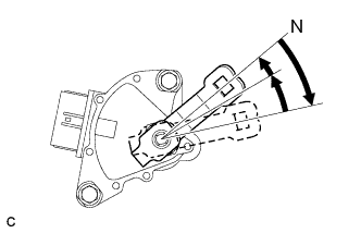
Temporarily install the control shaft lever to the manual valve shaft.
-
Turn the lever clockwise until it stops, then turn it counterclockwise 2 notches.
-
Remove the control shaft lever from the manual valve shaft.
-
Align the protruding part with the neutral basic line.
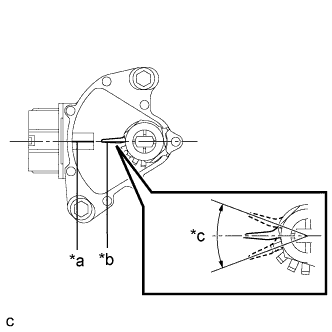
Text in Illustration *a Neutral Basic Line *b Protruding *c Range of Play Note
There is play on the nut stopper side (protruding part). Align the center point of the range of the play with the neutral basic line.
-
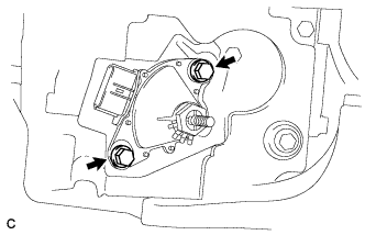
Tighten the 2 bolts in the order shown in the illustration.
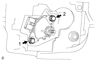
- Torque:
- 13 N*m { 133 kgf*cm, 10 ft.*lbf }
-
Using a screwdriver, secure the nut with the lock plate.
-
Install the control shaft lever, washer, and nut to the manual valve shaft.
- Torque:
- 13 N*m { 130 kgf*cm, 9 ft.*lbf }
-
Connect the connector to the shift lever position sensor.
-
-
CONNECT TRANSMISSION CONTROL CABLE ASSEMBLY
-
Move the shift lever to the N position.
-
Install a new clip to the control bracket.
-
Install the transmission control cable assembly to the control bracket.
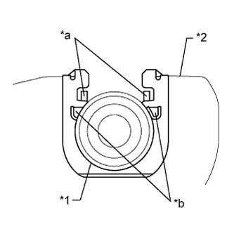
Text in Illustration *1 Transmission Control Cable Assembly *2 No. 1 Transmission Control Cable Bracket *a Claw A *b Claw B Note
-
Make sure that the A claws on the clip are securely fit into the bracket holes.
-
Make sure that the cable is securely installed inside the B claws of the clip.
-
-
Install the transmission control cable assembly to the control shaft lever with the nut.
- Torque:
- 15 N*m { 153 kgf*cm, 11 ft.*lbf }
-
-
INSPECT SHIFT LEVER POSITION SENSOR POSITION
-
Apply the parking brake.
-
Lock the wheels with chocks to secure the vehicle.
-
Turn the power switch on (READY).
-
Move the shift lever to D and release the brake.
Note
Be sure to apply the parking brake and lock the wheels with chocks to secure the vehicle.
-
Slowly move the shift lever to N and measure moving distance (A) of the shift lever from the original point to the gear activation point.
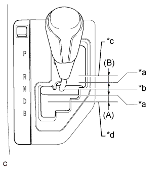
Text in Illustration *a Gear Activation Point *b N Position *c R Position *d D Position Note
Be sure to move the shift lever slowly.
-
Move the shift lever to R and release the brake.
Note
Be sure to apply the parking brake and lock the wheels with chocks to secure the vehicle.
-
Slowly move the shift lever to N and measure moving distance (B) of the shift lever from the original point to the vehicle activation point.
Note
Be sure to move the shift lever slowly.
-
Check that moving distances (A) and (B) shown in the illustration are almost the same.
Tech Tips
-
If moving distances (A) and (B) are almost the same, adjustment of the shift lever position is not necessary.
-
If moving distance (A) is shorter than (B), perform adjustment of the shift lever position [*1].
-
If moving distance (B) is shorter than (A), perform adjustment of the shift lever position [*2].
-
-
-
ADJUST SHIFT LEVER POSITION SENSOR POSITION
-
If moving distance (A) is shorter than (B).[*1]
-
Move the shift lever to N.
-
Loosen the 2 bolts.
-
Slightly turn the shift lever position sensor counterclockwise.
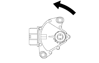
Tech Tips
If the shift lever is moved from R to N, the moving distance of the shift lever from the original point to the gear activation point becomes longer.
-
Tighten the 2 bolts in the order shown in the illustration.
- Torque:
- 13 N*m { 133 kgf*cm, 10 ft.*lbf }
-
Recheck the shift lever position sensor.
-
-
If moving distance (B) is shorter than (A) [*2]
-
Move the shift lever to N.
-
Loosen the 2 bolts.
-
Slightly turn the shift lever position sensor clockwise.
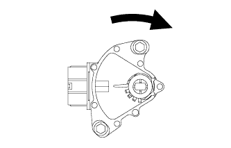
Tech Tips
If the shift lever is moved from D to N, the moving distance of the shift lever from the original point to the gear activation point becomes longer.
-
Tighten the 2 bolts in the order shown in the illustration.
- Torque:
- 13 N*m { 133 kgf*cm, 10 ft.*lbf }
-
Recheck the shift lever position sensor.
-
-
-
INSPECT SHIFT LEVER POSITION
-
While moving the shift lever from the N position to each position, check that the lever moves smoothly and that the shift position indicator comes on properly according to the shift lever position.
-
Put the vehicle into the READY-on state and check the following:
-
When the shift lever is moved to the D position, the vehicle moves forward.
-
When the shift lever is moved to the R position, the vehicle moves in reverse.
Note
The vehicle should not move when the shift position indicator is off.
-
-
-
ADJUST SHIFT LEVER POSITION
-
Move the shift lever to N.
-
Remove the console box Click here.
-
Disconnect the end of the transmission control cable assembly from the lower shift lever assembly.
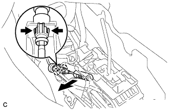
-
Slide the slider of the transmission control cable assembly in the direction indicated by the arrow and pull the lock piece outward.
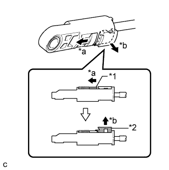
Text in Illustration *1 Slider *2 Lock Piece *a Slide *b Pull -
Install the end of the transmission control cable assembly to the lower shift lever assembly.
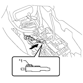
Text in Illustration *1 Lock Piece Note
-
Check that the lock piece is pulled up.
-
Install the cable end all the way to the base of the pin.
-
-
Push the lock piece into the adjuster case.
Note
-
Check that the park/neutral position switch and the shift lever are in neutral.
-
Securely push in the lock piece until the slider lock is engaged.
-
-
After adjusting the shift lever position, check the operation and function of the shift lever. If there is a problem, adjust the position again.
-
Install the console box Click here.
-
-
INSTALL ENGINE UNDER COVER RH
-
INSTALL FRONT WHEEL OPENING EXTENSION PAD RH
-
INSTALL ENGINE UNDER COVER LH
-
INSTALL FRONT WHEEL OPENING EXTENSION PAD LH