TRANSMISSION CONTROL CABLE INSTALLATION

-
INSTALL TRANSMISSION CONTROL CABLE ASSEMBLY
Note
Before installing the transmission control cable assembly, check that the shift lever position sensor and the shift lever are in neutral.
-
Pass the transmission control cable assembly from the cabin to the engine compartment.
-
Install the transmission control cable assembly with the 2 bolts.
- Torque:
- 5.0 N*m { 51 kgf*cm, 44 in.*lbf }
-
Install the dash panel insulator to the original position.
-
Connect the transmission control cable assembly to the 2 transmission control cable brackets.
-
Install a new clip to the No. 1 transmission control cable bracket.
-
Install the transmission control cable assembly to the No. 1 transmission control cable bracket
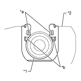
Text in Illustration *1 No. 1 Transmission control cable assembly *2 No. 1 transmission control cable bracket *a Claw A *b Claw B Note
-
Make sure that the claws A on the clip are securely fit into the bracket holes.
-
Make sure that the cable is securely installed inside of the claws B of the clip.
-
-
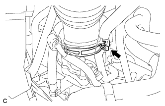
Connect the transmission control cable assembly to the control shaft lever with the nut.
- Torque:
- 15 N*m { 153 kgf*cm, 11 ft.*lbf }
-
Engage the 2 claws to connect the transmission control cable assembly.
-
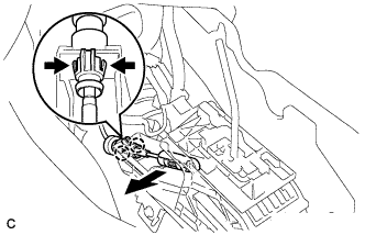
Slide the slider of the transmission control cable in the direction indicated by the arrow and pull the lock piece outward.
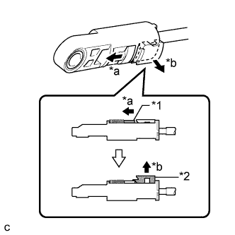
Text in Illustration *1 Slider *2 Lock Piece *a Slide *b Pull -
Install the end of transmission control cable assembly to the lower shift lever assembly.
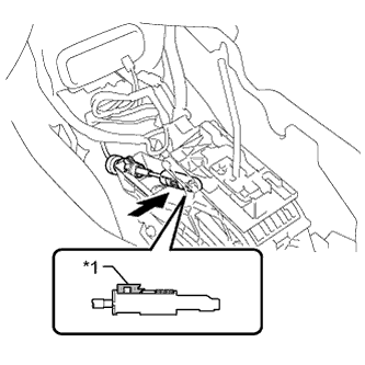
Text in Illustration *1 Lock Piece Note
-
Check that the lock piece is pulled up.
-
Install the cable end all the way to the base of the pin.
-
-
Push the lock piece into the adjuster case.
Note
-
Check that the shift lever position sensor and the shift lever are in neutral.
-
Securely push in the lock piece until the slider lock is engaged.
-
-
-
CONNECT NO. 1 PARKING BRAKE CABLE ASSEMBLY
-
Install the No. 1 parking brake cable assembly with the bolt and nut.
- Torque:
- Bolt
- 15 N*m { 153 kgf*cm, 11 ft.*lbf }
- Nut
- 5.4 N*m { 55 kgf*cm, 48 in.*lbf }
-
Install the floor carpet to the original position.
-
-
INSTALL ACCELERATOR PEDAL SENSOR ASSEMBLY
Note
-
Avoid physical shock to the accelerator pedal sensor assembly.
-
Do not disassemble the accelerator pedal sensor assembly.
-
This accelerator pedal does not require lubrication. Do not apply oil or other lubrication to the accelerator pedal sensor assembly. If applied, the accelerator pedal sensor assembly must be replaced.
-
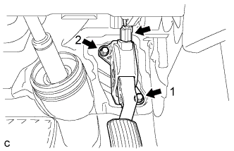
Temporarily install the accelerator pedal sensor assembly with the 2 bolts.
-
Tighten the 2 bolts in the order shown in the illustration.
- Torque:
- 5.4 N*m { 55 kgf*cm, 48 in.*lbf }
-
Connect the connector.
-
-
INSTALL AIRBAG SENSOR ASSEMBLY
-
INSTALL AIR CLEANER CASE SUB-ASSEMBLY
-
Insert the projection of the air cleaner case sub-assembly to the hole of the No. 2 air cleaner bracket as shown in the illustration.
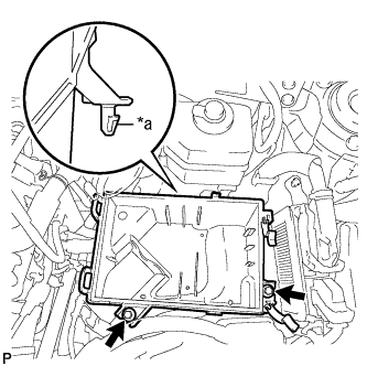
Text in Illustration *a Projection -
Tighten the 2 bolts.
- Torque:
- 5.0 N*m { 51 kgf*cm, 44 in.*lbf }
-
-
INSTALL AIR CLEANER FILTER ELEMENT
-
INSTALL AIR CLEANER CAP SUB-ASSEMBLY
-
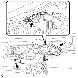
Disconnect the mass air flow meter connector and wire harness clamp from the air cleaner cap sub-assembly.
-
Disconnect the ventilation hose from the cylinder head cover.
-
Disconnect the connector and wire harness clamp.
-
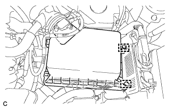
Release the 2 clamps and remove the air cleaner cap sub-assembly.
-
Disconnect the 2 fuel vapor feed hoses.
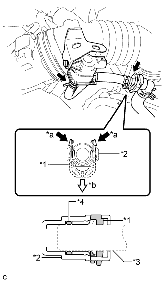
Text in Illustration *1 Retainer *2 Fuel Tube Connector *3 Pipe *4 O-ring *a Pinch *b Pull Note
-
Remove any dirt or foreign matter on the fuel tube connector before performing this work.
-
Do not allow any scratches or foreign matter to get on the parts when disconnecting them as the fuel tube connector has an O-ring that seals the pipe.
-
Perform this work by hand. Do not use any tools.
-
Protect the disconnected parts by covering them with plastic bags after disconnecting each fuel vapor feed hose.
-
-
Loosen the hose clamp and disconnect the air cleaner hose from the throttle with motor body assembly.
-
-
INSTALL INLET AIR CLEANER ASSEMBLY
-
Install the inlet air cleaner assembly with the 2 bolts.
- Torque:
- 8.0 N*m { 82 kgf*cm, 71 in.*lbf }
-
-
INSTALL COOL AIR INTAKE DUCT SEAL
-
Install the cool air intake duct seal with the 7 clips.
-
-
INSPECT SHIFT LEVER POSITION
-
While moving the shift lever from the N position to each position, check that the lever moves smoothly and that the shift position indicator comes on properly according to the shift lever position.
-
Put the vehicle into the READY-on state and check the following:
-
When the shift lever is moved to the D position, the vehicle moves forward.
-
When the shift lever is moved to the R position, the vehicle moves in reverse.
Note
The vehicle should not move when the shift position indicator is off.
-
-
-
ADJUST SHIFT LEVER POSITION
-
Move the shift lever to N.
-
Remove the console box Click here.
-
Disconnect the end of the transmission control cable assembly from the lower shift lever assembly.
-
Slide the slider of the transmission control cable assembly in the direction indicated by the arrow and pull the lock piece outward.
Text in Illustration *1 Slider *2 Lock Piece *a Slide *b Pull -
Install the end of the transmission control cable assembly to the lower shift lever assembly.
Text in Illustration *1 Lock Piece Note
-
Check that the lock piece is pulled up.
-
Install the cable end all the way to the base of the pin.
-
-
Push the lock piece into the adjuster case.
Note
-
Check that the park/neutral position switch and the shift lever are in neutral.
-
Securely push in the lock piece until the slider lock is engaged.
-
-
After adjusting the shift lever position, check the operation and function of the shift lever. If there is a problem, adjust the position again.
-
Install the console box Click here.
-