ENGINE UNIT REMOVAL

-
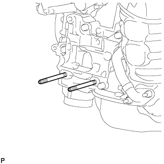
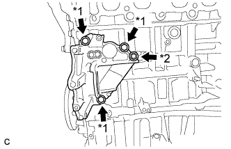
REMOVE ENGINE HANGERS
-
Remove the 2 bolts and 2 engine hangers.
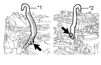
Text in Illustration *1 No. 1 Engine Hanger *2 No .2 Engine Hanger
-
-
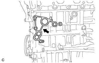
REMOVE ENGINE OIL LEVEL DIPSTICK GUIDE
-
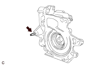
Remove the engine oil level dipstick.
-
Remove the bolt and engine oil level dipstick guide.
-
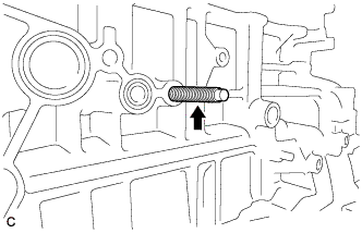
Remove the O-ring from the engine oil level dipstick guide.
-
-
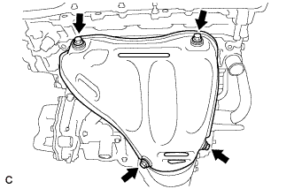
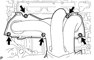
REMOVE NO. 1 EXHAUST MANIFOLD HEAT INSULATOR
-
Remove the 4 bolts and No. 1 exhaust manifold heat insulator.
-
-
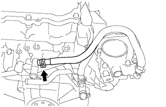
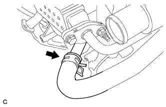
DISCONNECT NO. 1 WATER BY-PASS HOSE
-
Disconnect the No. 1 water by-pass hose.
-
-
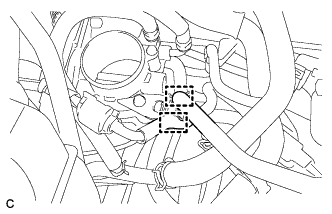
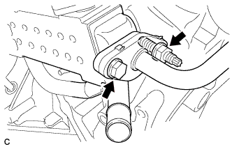
REMOVE THROTTLE WITH MOTOR BODY ASSEMBLY
-
Disconnect the 2 hoses.
-
Disconnect the throttle body connector.
-
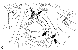
Disconnect the 2 water by-pass hoses from the throttle with motor body assembly.
-
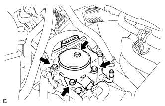
Remove the 4 bolts and the throttle body with fuel tube bracket.
-
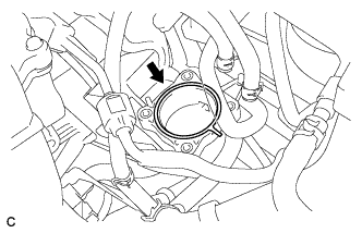
Remove the gasket from the intake manifold.
-
-
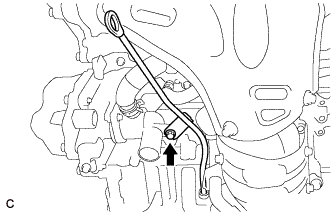
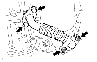
REMOVE NO. 2 EGR PIPE
-
Remove the 2 bolts, 2 nuts and No. 2 EGR pipe.
-
Remove the 2 gaskets.
-
-
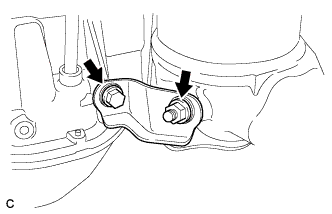
REMOVE MANIFOLD STAY
-
Remove the bolt, nut and manifold stay.
-
-
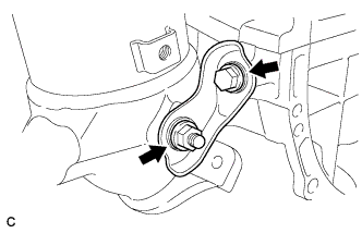
REMOVE NO. 2 MANIFOLD STAY
-
Remove the bolt, nut and No. 2 manifold stay.
-
-
REMOVE EXHAUST MANIFOLD CONVERTER SUB-ASSEMBLY
-
Remove the 5 nuts and exhaust manifold converter sub-assembly.
-
Remove the gasket.
-
-
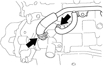
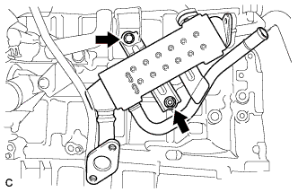
REMOVE EGR COOLER ASSEMBLY
-
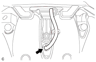
Disconnect the water by-pass hose.
-
Remove the bolt and nut.
-
Separate the 2 clamps.
-
Disconnect the No. 4 water by-pass hose and No. 6 water by-pass hose.
-
Remove the bolt, nut and separate the EGR cooler assembly from the engine.
-
-
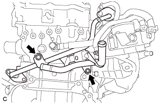
REMOVE NO. 1 EGR PIPE
-
Remove the 2 bolts and No. 1 EGR pipe.
-
-
REMOVE COMPRESSOR WITH MOTOR ASSEMBLY
-
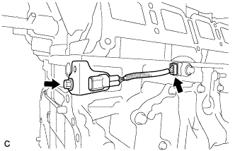
Disconnect connector B.
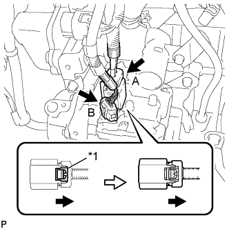
Text in Illustration *1 Green-colored Lock -
Release the green-colored lock and disconnect connector A as shown in the illustration.
CAUTION:
Wear insulated gloves when performing the following steps.
Note
Insulate the connector by sealing it with tape.
-
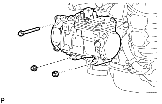
Remove the bolt and 2 nuts and compressor with motor assembly.
-
Using an E8 "TORX" socket, remove the 2 stud bolts.
-
-
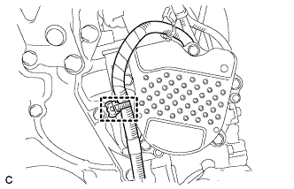
REMOVE ENGINE WATER PUMP ASSEMBLY
-
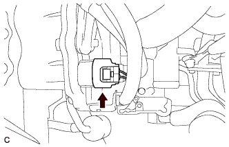
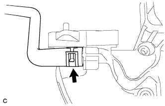
Disconnect the harness clamp.
-
Disconnect the connector from the engine water pump assembly.
-
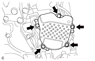
Remove the 5 bolts and engine water pump assembly.
-
Remove the gasket from the engine water pump assembly.
-
-
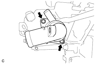
REMOVE WATER INLET SUB-ASSEMBLY
-
Remove the 2 bolts and water inlet sub-assembly.
-
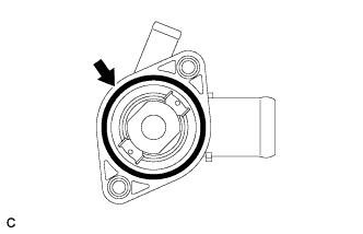
Remove the gasket from the water inlet sub-assembly.
-
-
REMOVE WATER INLET HOUSING
-
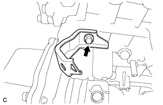
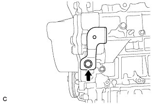
Remove the bolt and harness clamp bracket from the cylinder block.
-
Remove the bolt and harness clamp bracket from the water inlet housing.
-
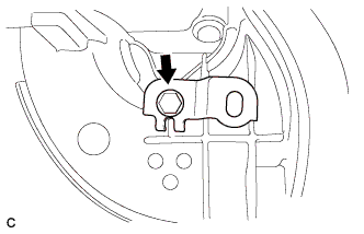
Remove the 3 bolts, nut, and water inlet housing.
Text in Illustration *1 Bolt *2 Nut -
Remove the gasket.
-
Using an E8 "TORX" socket wrench, remove the stud bolt from the cylinder block.
-
Using an E5 "TORX" socket wrench, remove the stud bolt from the water inlet housing.
-
-
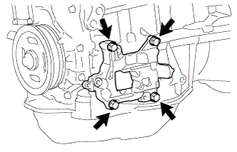
REMOVE NO. 1 COMPRESSOR MOUNTING BRACKET
-
Remove the 4 bolts and No. 1 compressor mounting bracket.
-
-
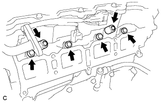
REMOVE FUEL DELIVERY PIPE SUB-ASSEMBLY
-
Disconnect the 4 fuel injector connectors.
-
Remove the 2 bolts, and then remove the fuel delivery pipe together with the 4 fuel injectors.
Note
Be careful not to drop the fuel injectors when removing the fuel delivery pipe.
-
Remove the 2 fuel delivery spacers from the cylinder head.
-
Remove the 4 injector vibration insulators from the cylinder head.
-
-
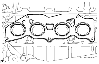
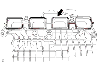
REMOVE INTAKE MANIFOLD
-
Remove the intake manifold from the vehicle.
-
Remove the gasket from the intake manifold.
-
Remove the bolt and wire harness clamp bracket.
-
Remove the vacuum hose from the intake manifold.
-
Remove the fuel vapor feed hose from the intake manifold.
-
-
REMOVE SENSOR WIRE
-
Disconnect the knock control sensor connector.
-
Remove the bolt and knock control sensor wire.
-
-
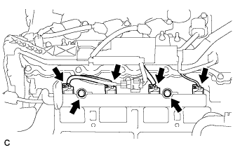
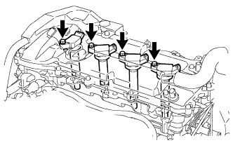
REMOVE IGNITION COIL ASSEMBLY
-
Disconnect the 4 ignition coil assembly connectors.
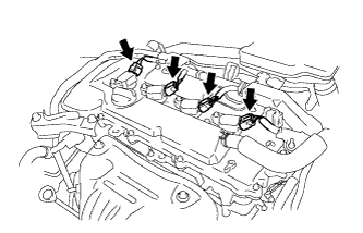
-
Remove the 4 bolts and 4 ignition coil assemblies.
-