CYLINDER HEAD GASKET REMOVAL

-
REMOVE TIMING CHAIN COVER SUB-ASSEMBLY
-
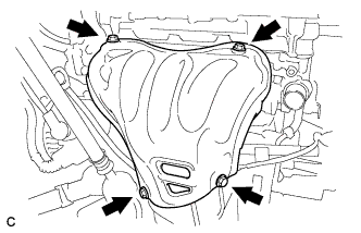
REMOVE NO. 1 EXHAUST MANIFOLD HEAT INSULATOR
-
Remove the 4 bolts and No. 1 exhaust manifold heat insulator.
-
-
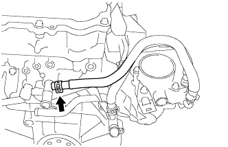
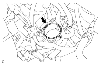
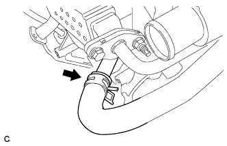
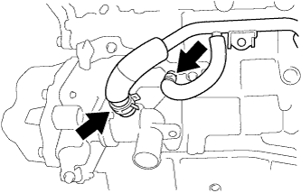
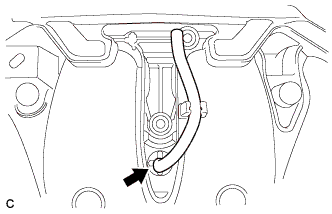
DISCONNECT NO. 1 WATER BY-PASS HOSE
-
Disconnect the No. 1 water by-pass hose.
-
-
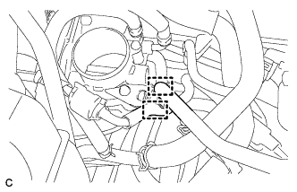
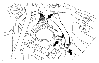
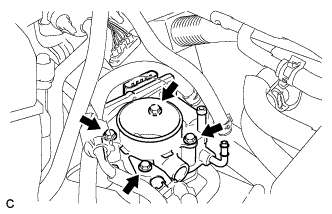
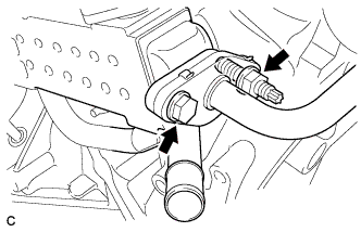
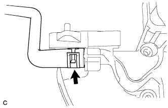
REMOVE THROTTLE WITH MOTOR BODY ASSEMBLY
-
Disconnect the 2 hoses.
-
Disconnect the throttle body connector.
-
Disconnect the 2 water by-pass hoses from the throttle with motor body assembly.
-
Remove the 4 bolts and the throttle body with fuel tube bracket.
-
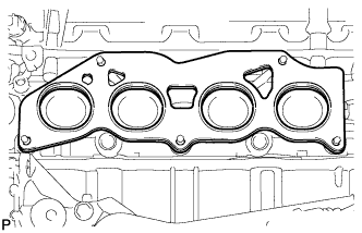
Remove the gasket from the intake manifold.
-
-
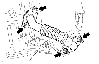
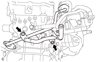
REMOVE NO. 2 EGR PIPE
-
Remove the 2 bolts, 2 nuts and No. 2 EGR pipe.
-
Remove the 2 gaskets.
-
-
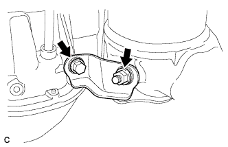
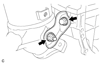
REMOVE MANIFOLD STAY
-
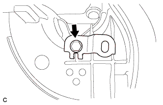
Remove the bolt, nut and manifold stay.
-
-
REMOVE NO. 2 MANIFOLD STAY
-
Remove the bolt, nut and No. 2 manifold stay.
-
-
REMOVE EXHAUST MANIFOLD CONVERTER SUB-ASSEMBLY
-
Remove the 5 nuts and exhaust manifold converter sub-assembly.
-
Remove the gasket.
-
-
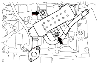
REMOVE EGR COOLER ASSEMBLY
-
Disconnect the water by-pass hose.
-
Remove the bolt and nut.
-
Separate the 2 clamps.
-
Disconnect the No. 4 water by-pass hose and No. 6 water by-pass hose.
-
Remove the bolt, nut and separate the EGR cooler assembly from the engine.
-
-
REMOVE NO. 1 EGR PIPE
-
Remove the 2 bolts and No. 1 EGR pipe.
-
-
REMOVE FUEL DELIVERY PIPE SUB-ASSEMBLY
-
Disconnect the 4 fuel injector connectors.
-
Remove the 2 bolts, and then remove the fuel delivery pipe together with the 4 fuel injectors.
Note
Be careful not to drop the fuel injectors when removing the fuel delivery pipe.
-
Remove the 2 fuel delivery spacers from the cylinder head.
-
Remove the 4 injector vibration insulators from the cylinder head.
-
-
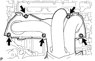
REMOVE INTAKE MANIFOLD
-
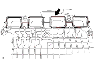
Remove the intake manifold from the vehicle.
-
Remove the gasket from the intake manifold.
-
Remove the bolt and wire harness clamp bracket.
-
Remove the vacuum hose from the intake manifold.
-
Remove the fuel vapor feed hose from the intake manifold.
-
-
SET NO. 1 CYLINDER TO TDC/COMPRESSION
-
Temporarily install the crankshaft pulley bolt.
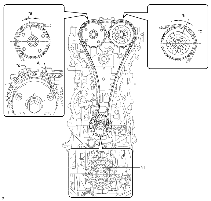
Text in Illustration *a Approximately 7° *b Approximately 32° *c Timing Mark *d Key Tech Tips
"A" is not a timing mark.
-
Rotate the crankshaft clockwise so that the timing marks on the crankshaft timing gear and camshaft timing gears are as shown in the illustration.
Tech Tips
If the timing marks do not align, rotate the crankshaft clockwise again and align the timing marks.
-
Remove the crankshaft pulley bolt.
-
-
REMOVE TIMING CHAIN GUIDE
-
Remove the bolt and timing chain guide.
-
-
REMOVE NO. 1 CHAIN TENSIONER ASSEMBLY
-
Allow the plunger to extend slightly, and then rotate the stopper plate counterclockwise to release the lock. Once the lock is released, push the plunger into the tensioner.
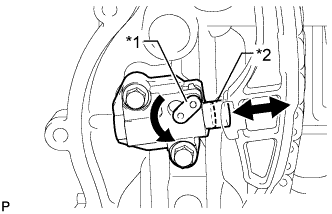
Text in Illustration *1 Stopper Plate *2 Plunger -
Move the stopper plate clockwise to set the lock, and insert a pin into the stopper plate hole.
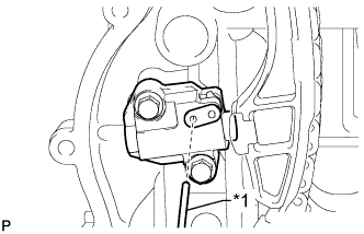
Text in Illustration *1 Pin -
Remove the 2 bolts, chain tensioner and gasket.
-
-
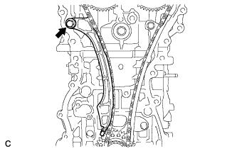
REMOVE CHAIN TENSIONER SLIPPER
-
Remove the bolt and chain tensioner slipper.
-
-
REMOVE CHAIN SUB-ASSEMBLY
-
Remove the chain sub-assembly.
-
-
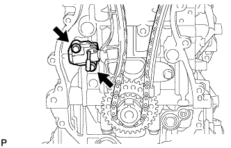
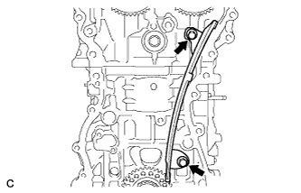
REMOVE NO. 1 CHAIN VIBRATION DAMPER
-
Remove the 2 bolts and chain vibration damper.
-
-
REMOVE CAMSHAFT TIMING GEAR ASSEMBLY
-
Hold the hexagonal portion of the camshaft with a wrench and remove the bolt and camshaft timing gear.
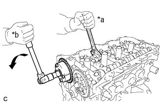
Text in Illustration *a Hold *b Turn Note
-
Be careful not to damage the cylinder head or spark plug tube with the wrench.
-
Do not disassemble the camshaft timing gear.
-
-
-
REMOVE CAMSHAFT TIMING SPROCKET
-
Hold the hexagonal portion of the camshaft with a wrench and remove the bolt and camshaft timing sprocket.
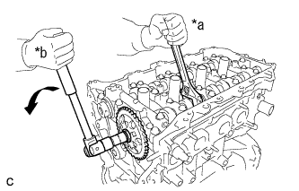
Text in Illustration *a Hold *b Turn Note
Be careful not to damage the cylinder head or spark plug tube with the wrench.
-
-
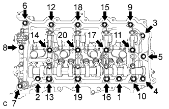
REMOVE CAMSHAFT HOUSING SUB-ASSEMBLY
-
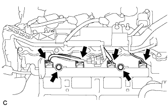
Uniformly loosen and remove the 20 bearing cap bolts in the sequence shown in the illustration.
-
Remove the camshaft housing by prying between the cylinder head and camshaft housing with a screwdriver.
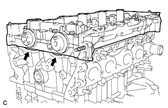
Tech Tips
Tape the screwdriver tip before use.
Note
Be careful not to damage the contact surfaces of the cylinder head and camshaft housing.
-
-
REMOVE CAMSHAFT BEARING CAP
-
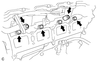
Remove the 11 bearing cap bolts in the sequence shown in the illustration.
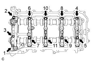
-
Remove the 5 bearing caps.
Tech Tips
Arrange the removed parts in the correct order.
-
-
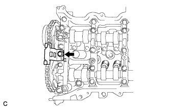
REMOVE OIL CONTROL VALVE FILTER
-
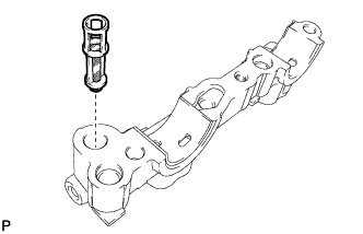
Remove the oil control valve filter from the No. 1 camshaft bearing cap.
-
-
REMOVE NO. 1 CAMSHAFT BEARING
-
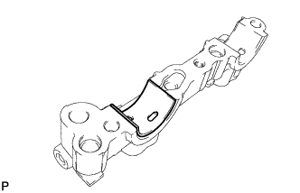
Remove the No. 1 camshaft bearing from the No. 1 camshaft bearing cap.
-
-
REMOVE CAMSHAFT
-
Remove the camshaft and No. 2 camshaft.
-
-
REMOVE NO. 2 CAMSHAFT BEARING
-
Remove the No. 2 camshaft bearing from the camshaft housing sub-assembly.
-
-
REMOVE NO. 1 VALVE ROCKER ARM SUB-ASSEMBLY
-
Remove the 16 valve rocker arms from the cylinder head.
Tech Tips
Arrange the removed parts in the correct order.
-
-
REMOVE VALVE LASH ADJUSTER ASSEMBLY
-
Remove the 16 valve lash adjusters from the cylinder head.
Tech Tips
Arrange the removed parts in the correct order.
-
-
REMOVE VALVE STEM CAP
-
Remove the 16 valve stem caps from the cylinder head.
Tech Tips
Arrange the removed parts in the correct order.
-
-
REMOVE CYLINDER HEAD SUB-ASSEMBLY
-
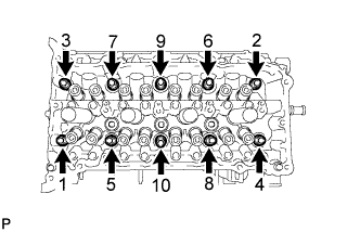
Using a 10 mm bi-hexagon wrench, uniformly loosen the 10 bolts in the sequence shown in the illustration. Remove the 10 cylinder head bolts and plate washers.
Tech Tips
Be sure to keep the removed parts separate for each installation position.
Note
-
Be careful not to drop washers into the cylinder head.
-
Head warpage or cracking could result from removing bolts in the incorrect order.
-
-
Remove the cylinder head.
-
-
REMOVE CYLINDER HEAD GASKET
-
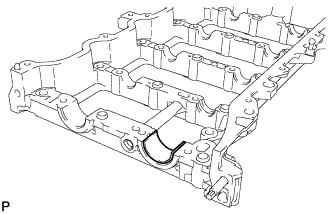
Remove the cylinder head gasket from the cylinder block.
-