CAMSHAFT INSTALLATION

Tech Tips
Perform "Inspection After Repair" after replacing the camshaft, No. 2 camshaft or camshaft timing gear assembly Click here.
-
INSPECT CAMSHAFT TIMING GEAR ASSEMBLY
-
Align and attach the knock pin of the No. 1 camshaft with the pin hole of the camshaft timing gear.
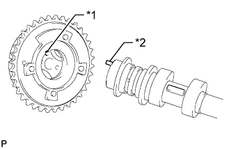
Text in Illustration *1 Pin Hole *2 Knock Pin -
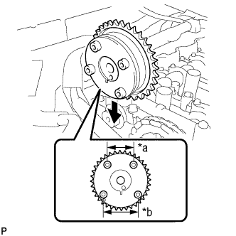
Check that there is no clearance between the camshaft timing gear and camshaft flange.
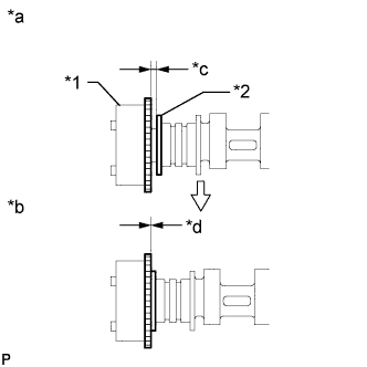
Text in Illustration *1 Camshaft Timing Gear *2 Flange *a INCORRECT *b CORRECT *c Clearance *d No Clearance -
Secure the camshaft in place by hand, and then install the installation bolt of the camshaft timing gear by hand.
Note
Do not use any tools to install the bolt. If the bolt is installed using a tool, the lock pin will be damaged.
-
Check the lock of the camshaft timing gear.
-
Make sure that the camshaft timing gear is locked.
Note
Be careful not to damage the camshaft.
-
-
Release the lock pin.
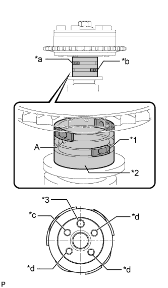
Text in Illustration *1 Rubber *2 Vinyl Tape *3 Knock Pin *a Retard Side Path *b Advance Side Path *c Open *d Close -
Clean the camshaft journal with non-residue solvent.
-
Cover the 4 oil paths of the cam journal with vinyl tape as shown in the illustration.
Tech Tips
There are 4 oil paths in the grooves of the camshaft. Plug three of the paths with pieces of rubber.
-
Open a hole at port A shown in the illustration.
-
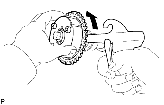
While applying approximately 200 kPa (2.0 kgf/ cm2, 29 psi) of air pressure to the oil path, forcibly turn the camshaft timing gear assembly in the advance direction (counterclockwise).
CAUTION:
Cover the paths with a piece of cloth when applying pressure to keep oil from spraying.
Note
Do not allow the camshaft timing gear assembly to lock. If it locks, release the lock pin again.
Tech Tips
-
The camshaft timing gear assembly may be turned in the advance direction without applying any force.
-
If enough air pressure cannot be applied because of air leakage from the port, releasing the lock pin may be difficult.
-
-
-
Check for smooth rotation.
-
Turn the camshaft timing gear within its movable range (26.5 to 28.5°) 2 or 3 times, but do not turn it to the most retarded position. Make sure that the gear turns smoothly.
Note
Do not allow the camshaft timing gear assembly to lock.
If it locks, release the lock pin again.
-
-
Remove the vinyl tape and rubber pieces from the camshaft.
-
Remove the bolt and camshaft timing gear.
-
-
INSTALL NO. 2 CAMSHAFT BEARING
-
Clean the No. 2 camshaft bearing.
-
Install the No. 2 camshaft bearing to the camshaft housing sub-assembly.
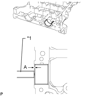
Text in Illustration *1 Vernier Caliper -
Using a vernier caliper, measure the distance between the camshaft housing edge and the No. 2 camshaft bearing edge.
Standard distance 1.15 to 1.85 mm (0.0453 to 0.0728 in.)
-
-
INSTALL NO. 1 CAMSHAFT BEARING
-
Clean the No. 1 camshaft bearing.
-
Install the No. 1 camshaft bearing to the No. 1 camshaft bearing cap.
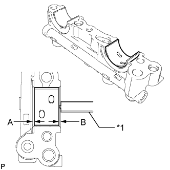
Text in Illustration *1 Vernier Caliper -
Using a vernier caliper, measure the distance between the No. 1 camshaft bearing cap edge and the No. 1 camshaft bearing edge.
Standard dimension A - B or B - A 0 to 0.7 mm (0 to 0.0276 in.)
-
-
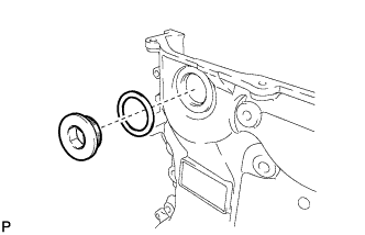
INSTALL OIL CONTROL VALVE FILTER
-
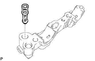
Install the oil control valve filter to the No. 1 camshaft bearing cap.
-
-
INSTALL CAMSHAFT TIMING SPROCKET
-
Secure the camshaft in a vice by clamping the hexagonal part using aluminum plates.
Note
Do not damage the camshaft by tightening the vice excessively.
-
Install the camshaft timing sprocket to the No. 2 camshaft with the bolt.
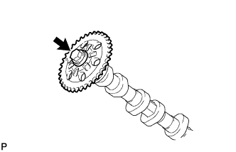
- Torque:
- 85 N*m { 867 kgf*cm, 63 ft.*lbf }
Note
Do not damage the No. 2 camshaft or camshaft timing sprocket.
-
-
SET NO. 1 CYLINDER TO TDC/COMPRESSION
-
Turn the crankshaft pulley until its timing notch (groove) and the timing mark "0" of the timing chain cover are aligned.
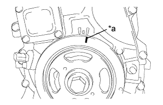
Text in Illustration *a Timing Notch
-
-
INSTALL NO. 2 CAMSHAFT
-
Make sure that the valve rocker arms are installed as shown in the illustration.
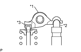
Text in Illustration *1 Valve Rocker Arm *2 Valve Lash Adjuster *3 Valve Stem Cap -
Clean the camshaft journals.
-
Apply a light coat of engine oil to the camshaft journals, camshaft housings and bearing caps.
-
Hold up the chain and align the timing mark and the paint mark, and install the No. 2 camshaft.
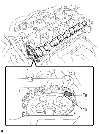
Text in Illustration *a Paint Mark *b Timing mark Tech Tips
Perform "Inspection After Repair" after replacing the No. 2 camshaft Click here.
-
-
INSTALL CAMSHAFT
-
Make sure that the valve rocker arms are installed as shown in the illustration.
Text in Illustration *1 Valve Rocker Arm *2 Valve Lash Adjuster *3 Valve Stem Cap -
Clean the camshaft journals.
-
Apply a light coat of engine oil to the camshaft journals, camshaft housings and bearing caps.
-
Install the camshaft to the camshaft housing as shown in the illustration.
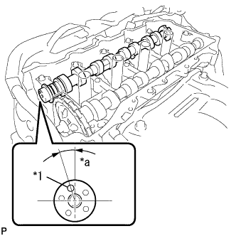
Text in Illustration *1 Knock Pin *a Approximately 17° Tech Tips
Perform "Inspection After Repair" after replacing the camshaft Click here.
-
-
INSTALL CAMSHAFT BEARING CAP
-
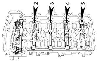
Confirm the marks and numbers on the camshaft bearing caps and place them in their proper positions and directions.
-
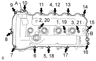
Using several steps, uniformly tighten the 10 bolts in the sequence shown in the illustration.
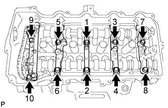
- Torque:
- 27 N*m { 275 kgf*cm, 20 ft.*lbf }
-
Using several steps, uniformly tighten the 11 bolts in the sequence shown in the illustration.
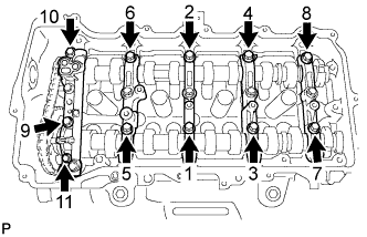
- Torque:
- 16 N*m { 163 kgf*cm, 12 ft.*lbf }
-
Check the torque of each bolt again.
-
-
INSTALL CAMSHAFT TIMING GEAR ASSEMBLY
-
Check the camshaft timing gear position.
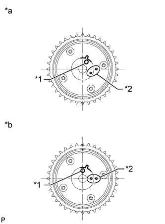
Text in Illustration *1 Knock Pin Hole *2 Alignment Mark *a Advanced Position *b Retarded Position Note
-
If the camshaft timing gear is set to the advanced position, do not let the camshaft timing gear rotate clockwise during installation.
-
If the camshaft timing gear has rotated to the most retarded position, make sure to release the lock pin and set the camshaft timing gear to the most advanced position before tightening the camshaft timing gear.
-
-
Install the camshaft timing gear as shown in the illustration.
Text in Illustration *a Narrow *b Wide -
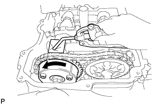
Turn the camshaft timing gear approximately 180° counterclockwise.
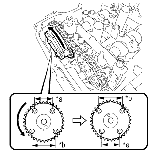
Text in Illustration *a Narrow *b Wide -
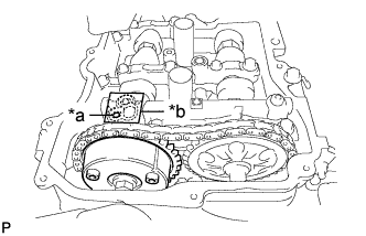
Align the paint mark with the timing mark to install the chain.
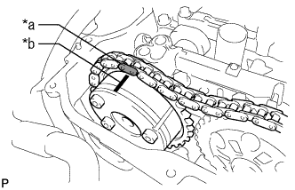
Text in Illustration *a Paint Mark *b Timing mark -
Align and attach the knock pin of the camshaft with the pin hole of the camshaft timing gear.
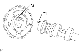
Text in Illustration *1 Knock Pin *a Knock Pin Hole -
Check that there is no clearance between the camshaft timing gear and camshaft flange.
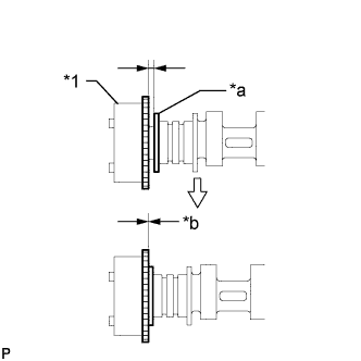
Text in Illustration *1 Camshaft Timing Gear *a Camshaft Flange *b No Clearance -
Secure the camshaft in place by hand, and then install the installation bolt of the camshaft timing gear by hand.
Note
Do not use any tools to install the bolt. If the bolt is installed using a tool, the lock pin will be damaged.
-
If the lock pin has not been released, release it.
-
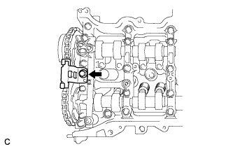
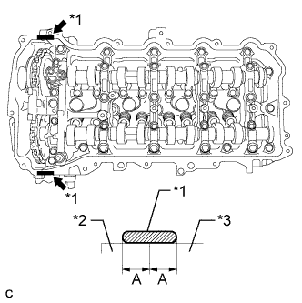
After cleaning and degreasing the intake side VVT oil hole on the No. 1 camshaft bearing cap, completely seal the oil hole with adhesive tape or equivalent as shown in the illustration to prevent air from leaking.
Text in Illustration *1 Adhesive Tape Sealing Area *a Make a Hole Note
Be sure to seal the oil hole completely because air leaks due to insufficient sealing will prevent the lock pin from being released.
-
Make a hole in the adhesive tape covering the oil hole as shown in the illustration. (Procedure A)
-
Apply approximately 200 kPa (2.0 kgf/ cm2, 29 psi) of air pressure to the hole made in procedure A to release the lock pin.
Note
-
If air leaks out, reattach the adhesive tape.
-
Cover the oil hole with a piece of cloth when applying air pressure to prevent oil from spraying.
-
-
Forcibly turn the camshaft timing gear in the advance direction (counterclockwise).
Tech Tips
Depending on the air pressure applied, the camshaft timing gear may turn in the advance direction without assistance by hand.
-
Remove the adhesive tape from the No. 1 camshaft bearing cap.
-
-
Using a wrench to hold the hexagonal portion of the camshaft, install the bolt.
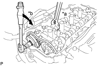
Text in Illustration *a Hold *b Turn - Torque:
- 85 N*m { 867 kgf*cm, 63 ft.*lbf }
Note
Be careful not to damage the cylinder head or spark plug tube with the wrench.
-
Check that each timing mark of the camshaft timing gear and camshaft timing sprocket are aligned with each timing mark located as shown in the illustration.
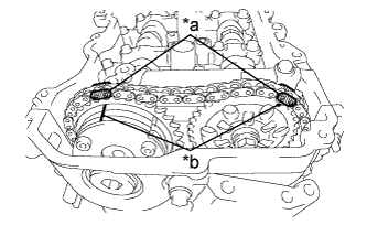
Text in Illustration *a Paint Mark *b Timing Mark Tech Tips
Perform "Inspection After Repair" after replacing the camshaft timing gear assembly Click here.
-
-
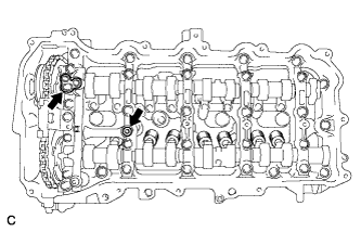
ADD ENGINE OIL
-
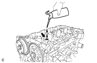
Add 50 cc (3.1 cu. in) of engine oil into the oil hole shown in the illustration.
Note
-
Oil must be added if the lash adjusters were removed.
-
Make sure that the low pressure chamber and oil paths of the lash adjusters are full of engine oil.
-
-
-
INSTALL TIMING CHAIN GUIDE
-
Install the timing chain guide with the bolt.
- Torque:
- 21 N*m { 214 kgf*cm, 15 ft.*lbf }
-
-
INSTALL NO. 1 CHAIN TENSIONER ASSEMBLY
-
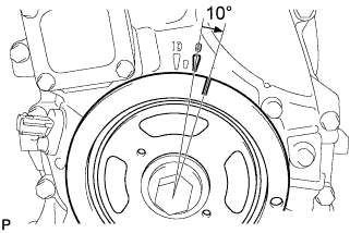
Turn the crankshaft approximately 10° clockwise.
-
Install a new gasket and the No. 1 chain tensioner assembly with the 2 bolts.
- Torque:
- 10 N*m { 102 kgf*cm, 7 ft.*lbf }
Note
Make sure not to drop the gasket inside the timing chain cover.
-
Remove the pin from the stopper plate.
-
-
SET NO. 1 CYLINDER TO TDC/COMPRESSION
-
Turn the crankshaft pulley until its timing notch (groove) and the timing mark "0" of the timing chain cover are aligned.
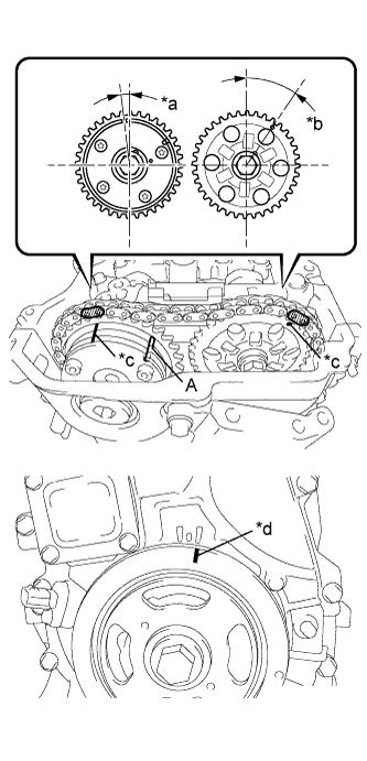
Text in Illustration *a Approximately 7° *b Approximately 32° *c Timing Mark *d Timing Notch -
Check that the timing marks of the camshaft timing gears are as shown in the illustration. If not, turn the crankshaft 1 revolution (360°) to align the timing marks as shown in the illustration.
Tech Tips
"A" is not a timing mark.
-
-
INSTALL TIMING CHAIN COVER PLATE
-
Install a new gasket and the timing chain cover plate with the 4 bolts.
- Torque:
- 10 N*m { 102 kgf*cm, 7 ft.*lbf }
-
-
INSTALL OIL PUMP RELIEF VALVE PLUG
-
Using a 14 mm hexagon wrench, install a new gasket and the oil pump relief valve plug.
- Torque:
- 30 N*m { 306 kgf*cm, 22 ft.*lbf }
-
-
INSTALL CYLINDER HEAD COVER SUB-ASSEMBLY
-
Apply a light coat of engine oil to 2 new gaskets.
-
Install the 2 gaskets to the camshaft bearing caps.
-
Install a new gasket to the cylinder head cover sub-assembly.
Note
Remove any oil from the contact surface.
-
Apply seal packing as shown in the illustration.
Seal packing Toyota Genuine Seal Packing Black, Three Bond 1207B or equivalent Standard seal diameter 3.0 to 6.0 mm (0.118 to 0.236 in.) Application width A 5.0 mm (0.197 in.) Text in Illustration *1 Seal Packing *2 Timing Chain Cover *3 Camshaft Housing Note
-
Remove any oil from the contact surface.
-
Install the cylinder head cover within 3 minutes after applying seal packing.
-
-
Align the cylinder head cover with pin A. Then align the cylinder head cover with pin B and install the cylinder head cover sub-assembly.
-
Install 3 new seal washers and the 16 bolts, and then tighten the bolts in the order shown in the illustration.
- Torque:
- 12 N*m { 122 kgf*cm, 9 ft.*lbf }
Note
Do not apply oil for at least 2 hours after the installation.
-
-
INSTALL IGNITION COIL ASSEMBLY
-
Install the 4 ignition coil assemblies with the 4 bolts.
- Torque:
- 10 N*m { 102 kgf*cm, 7 ft.*lbf }
Tech Tips
Perform "Inspection After Repair" after replacing the ignition coil assembly Click here.
-
Connect the 4 ignition coil assembly connectors.
-
-
CONNECT ENGINE WIRE
-
Install the engine wire to the engine with the 5 bolts and 3 nuts.
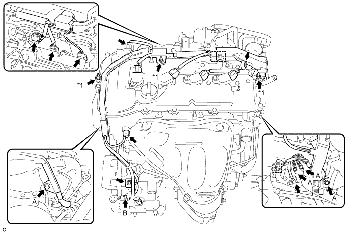
Text in Illustration *1 Nut - - - Torque:
- Bolt A
- 8.0 N*m { 82 kgf*cm, 71 in.*lbf }
- Bolt B
- 10.0 N*m { 102 kgf*cm, 7 ft.*lbf }
- Nut
- 8.0 N*m { 82 kgf*cm, 71 in.*lbf }
-
Connect the 8 connectors and 2 harness clamps.
-
-
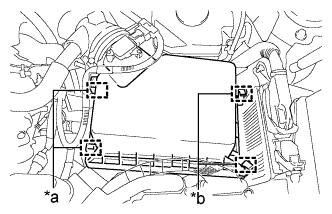
INSTALL NO. 2 ENGINE ROOM RELAY BLOCK (for LHD)
-
Install the No. 2 engine room relay block with the bolt and harness clamp.
- Torque:
- 8.0 N*m { 82 kgf*cm, 71 in.*lbf }
-
Install the front fender liner RH with the screw.
-
-
INSTALL INVERTER RESERVE TANK ASSEMBLY (for LHD)
-
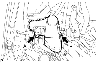
Temporarily install the inverter reserve tank assembly with the 2 bolts.
-
Tighten the 2 bolts to the inverter reserve tank assembly in the order the bolt A and bolt B.
- Torque:
- 10 N*m { 102 kgf*cm, 7 ft.*lbf }
-
-
INSTALL ENGINE MOVING CONTROL ROD SUB-ASSEMBLY
-
When the engine moving control rod has been replaced.
-
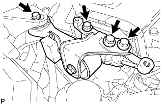
Temporarily install the engine moving control rod sub-assembly with the 4 bolts.
-
Fully tighten the engine moving control rod sub-assembly with the bolts except bolt A.
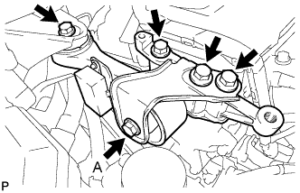
- Torque:
- 38 N*m { 387 kgf*cm, 28 ft.*lbf }
-
Using SST, fully tighten the bolt A.
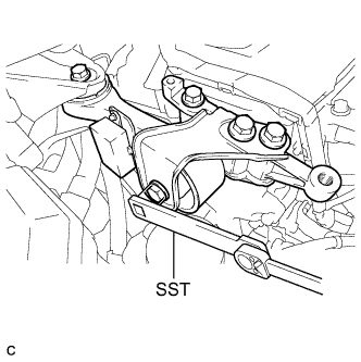
- SST
- 09961-00950
- Torque:
- without SST
- 52 N*m { 530 kgf*cm, 38 ft.*lbf }
- with SST
- 33 N*m { 340 kgf*cm, 25 ft.*lbf }
Note
-
The "with SST" torque value is effective when using SST with a fulcrum length of 150 mm (5.91 in.) and a torque wrench with a fulcrum length of 260 mm (10.24 in.) Click here.
-
The "with SST" torque value is effective when SST is parallel to the torque wrench.
-
Fully tighten bolt A using SST.
-
-
When the engine moving control rod has been reused.
-
Temporarily install the engine moving control rod sub-assembly with the 4 bolts.
-
Fully tighten the engine moving control rod sub-assembly with the 4 bolts.
- Torque:
- 38 N*m { 387 kgf*cm, 28 ft.*lbf }
-
-
-
CONNECT EARTH WIRE
-
Install the earth wire with the bolt.
- Torque:
- 8.0 N*m { 82 kgf*cm, 71 in.*lbf }
-
-
INSTALL NO. 2 ENGINE MOUNTING STAY RH
-
Install the No. 2 engine mounting stay RH with the 2 bolts.
- Torque:
- 38 N*m { 387 kgf*cm, 28 ft.*lbf }
-
-
INSTALL AIR CLEANER CASE SUB-ASSEMBLY
-
Insert the projection of the air cleaner case sub-assembly to the hole of the No. 2 air cleaner bracket as shown in the illustration.
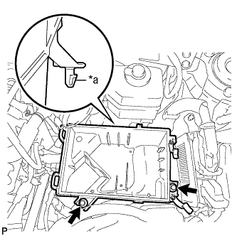
Text in Illustration *a Projection -
Tighten the 2 bolts.
- Torque:
- 5.0 N*m { 51 kgf*cm, 44 in.*lbf }
-
-
INSTALL AIR CLEANER FILTER ELEMENT
-
Install the air cleaner filter element.
Note
Install the air cleaner filter element with the printed side facing the vehicle front.
-
-
INSTALL AIR CLEANER CAP SUB-ASSEMBLY
-
Install the air cleaner hose with the hose clamp.
-
Connect the 2 fuel vapor feed hoses.
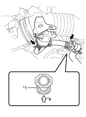
Text in Illustration *1 Retainer *a Push Note
-
Check that there are no scratches or foreign matter around the connected part of the fuel tube connector and pipe before performing this work.
-
Connect the quick connector and push the retainer in until the retainer makes a "click" sound to lock the claws of the retainer.
-
After connecting the fuel vapor feed hose to the fuel tube connector, check that the fuel vapor feed hose is securely connected by pulling on the fuel tube connector and the fuel vapor feed hose.
-
-
Connect the 2 hinges of the air cleaner cap subassembly.
Text in Illustration *a Hinge *b Clamp -
Install the air cleaner cap sub-assembly with the 2 clamps.
-
Connect the wire harness clamp and connector.
-
Connect the ventilation hose to the cylinder head cover.
-
Connect the mass air flow meter connector and wire harness clamp to the air cleaner cap sub-assembly.
-
-
INSTALL INLET AIR CLEANER ASSEMBLY
-
Install the inlet air cleaner assembly with the 2 bolts.
- Torque:
- 8.0 N*m { 82 kgf*cm, 71 in.*lbf }
-
-
INSPECT FOR OIL LEAK
-
INSTALL FRONT FENDER APRON SEAL RH
-
INSTALL ENGINE UNDER COVER RH
-
INSTALL FRONT WHEEL OPENING EXTENSION PAD RH
-
INSTALL NO. 1 ENGINE COVER SUB-ASSEMBLY
-
Engage the 3 pins and install the No. 1 engine cover sub-assembly.
-
-
INSTALL COOL AIR INTAKE DUCT SEAL
-
Install the cool air intake duct seal with the 7 clips.
-
-
INSTALL FRONT WHEEL RH
- Torque:
- 103 N*m { 1049 kgf*cm, 76 ft.*lbf }